Happy New Year! It’s been more than six months since my last blog entry, but I have kept very busy fitting avionics into the shell. At the beginning of this phase of the project, I had a general idea of where the various pieces (main instrument panel, mode control panel, EFIS modules, glareshield, and FMC/CDU bay) would wind up, but had to work out a large number of details about how the major components would fit together.
The dimensions of a 737NG cockpit are virtually identical to that of the classic model, with one major exception: the FMC/CDU bay of the NG model is almost two inches wider than that of the older models, to accommodate the lower EICAS screen between the two CDUs. The rudder pedal bays are slightly smaller to accommodate this change.
I had two FMC/CDU pedestals, a narrow Boeing one that came with my cockpit and a wider, NG size model made for the simulation market by Flightdeck Solutions.
The problem could not be easily solved. The FDS pedestal was too wide to fit into the available space without rubbing against the rudder pedals, and the Boeing one was too narrow to accommodate all of the components. So I decided to use the top of the FDS pedestal mated to the bottom of the Boeing unit.
I would have to be fairly precise with the cuts. The mated pieces would have to be high enough at the forward edge to meet the main instrument panel (“MIP”) at the right place, and low enough to join up with the throttle quadrant at the aft edge. Furthermore, the rudder pedals needed to be able to clear the enlarged pedestal at the aft end of their travel, and the top, FDS portion would also have to be deep enough to accommodate the FDS CDUs, which sit on wedge shaped bases to allow them to be used as freestanding units on the desktop.
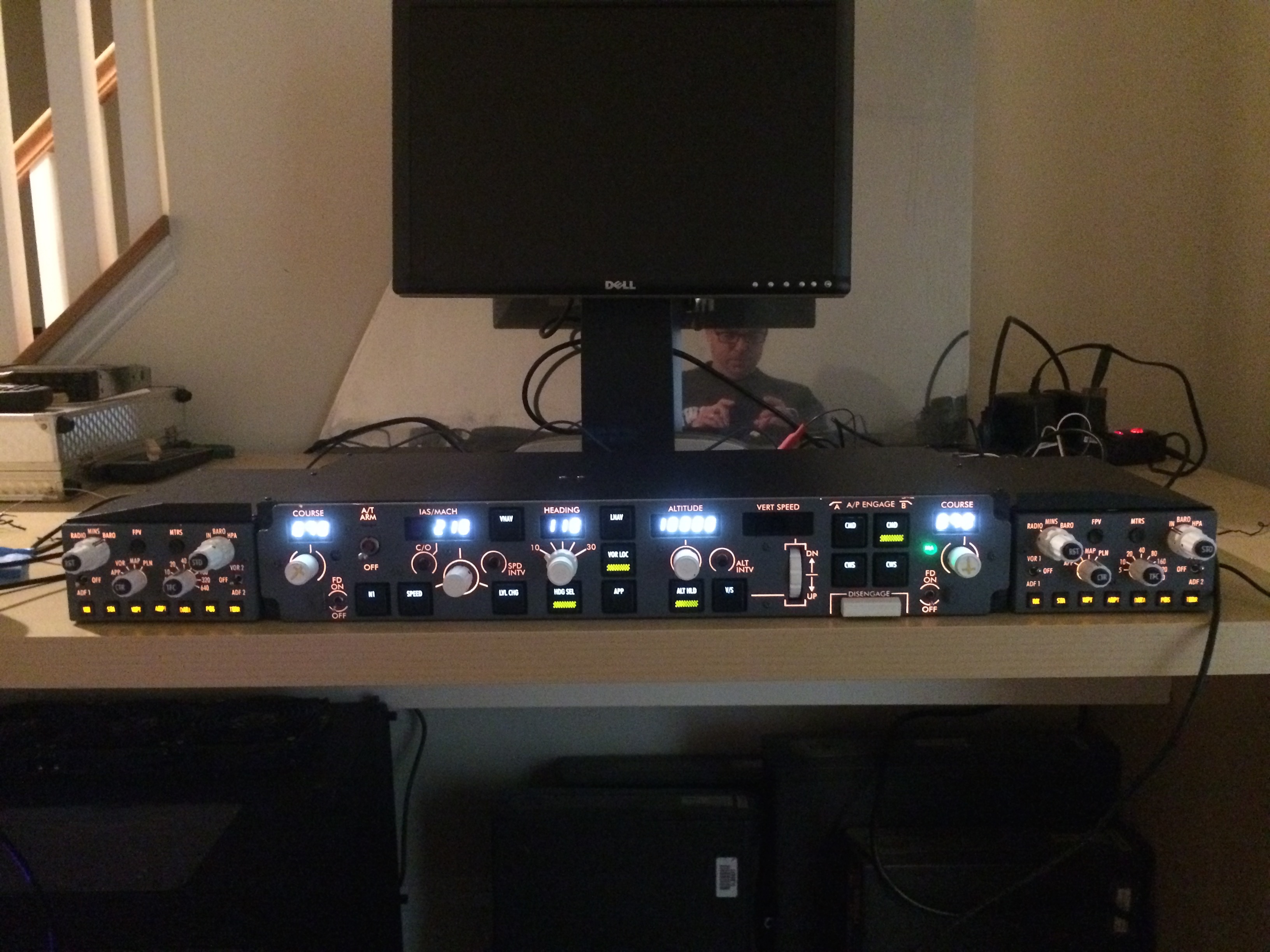
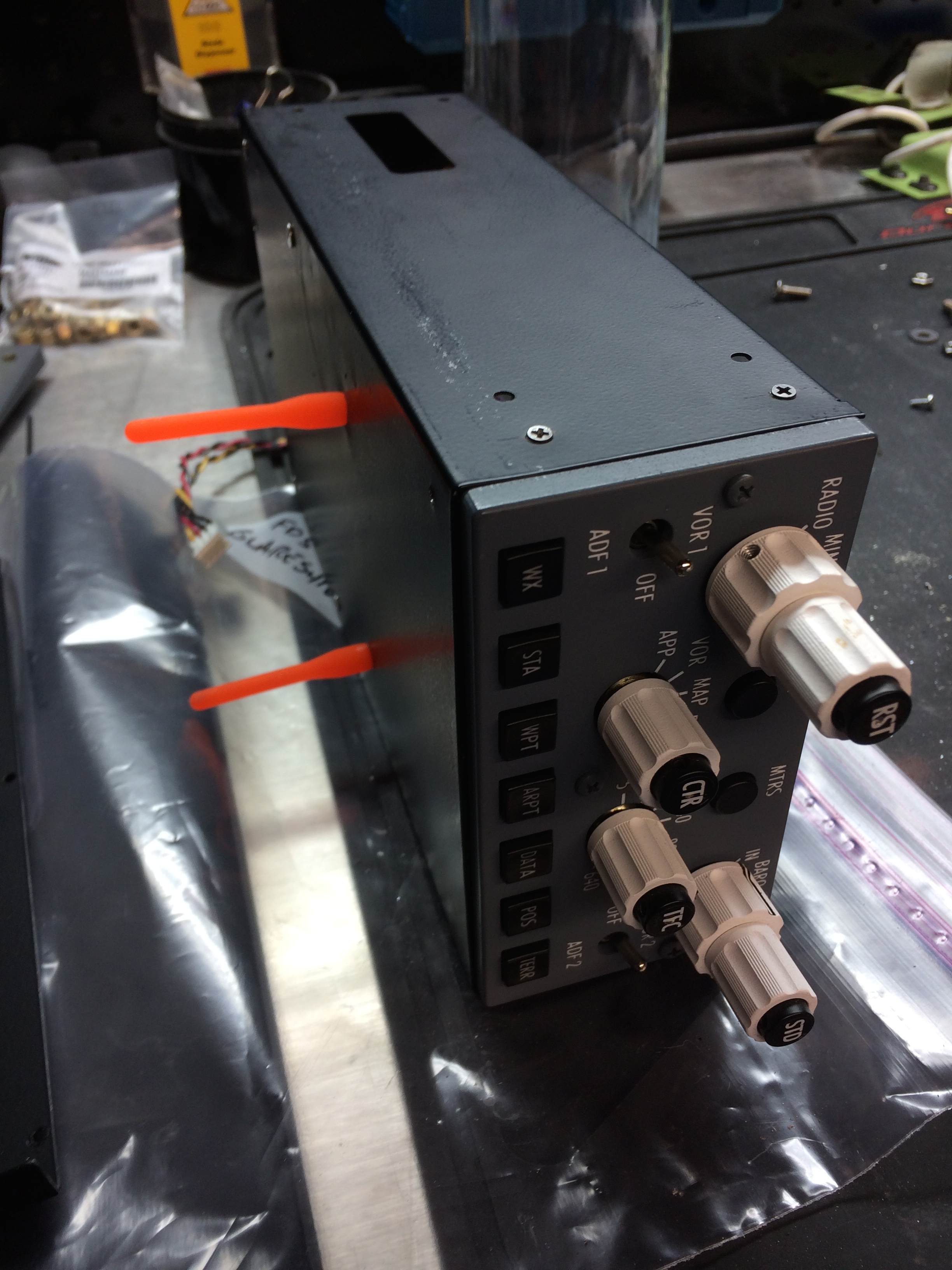
My original plan was to mount the MIP first, so that I would know exactly where to mount the FDS top onto the Boeing bottom. The only problem with this was that the mode control panel (the “MCP” or autopilot control panel) and EFIS control panels needed to be mounted first so that the top of the MIP would be fitted correctly. As I plan to do for all avionics, this unit was first bench tested and fully configured prior to installation. Troubleshooting these units is so much easier before they are installed in the shell.
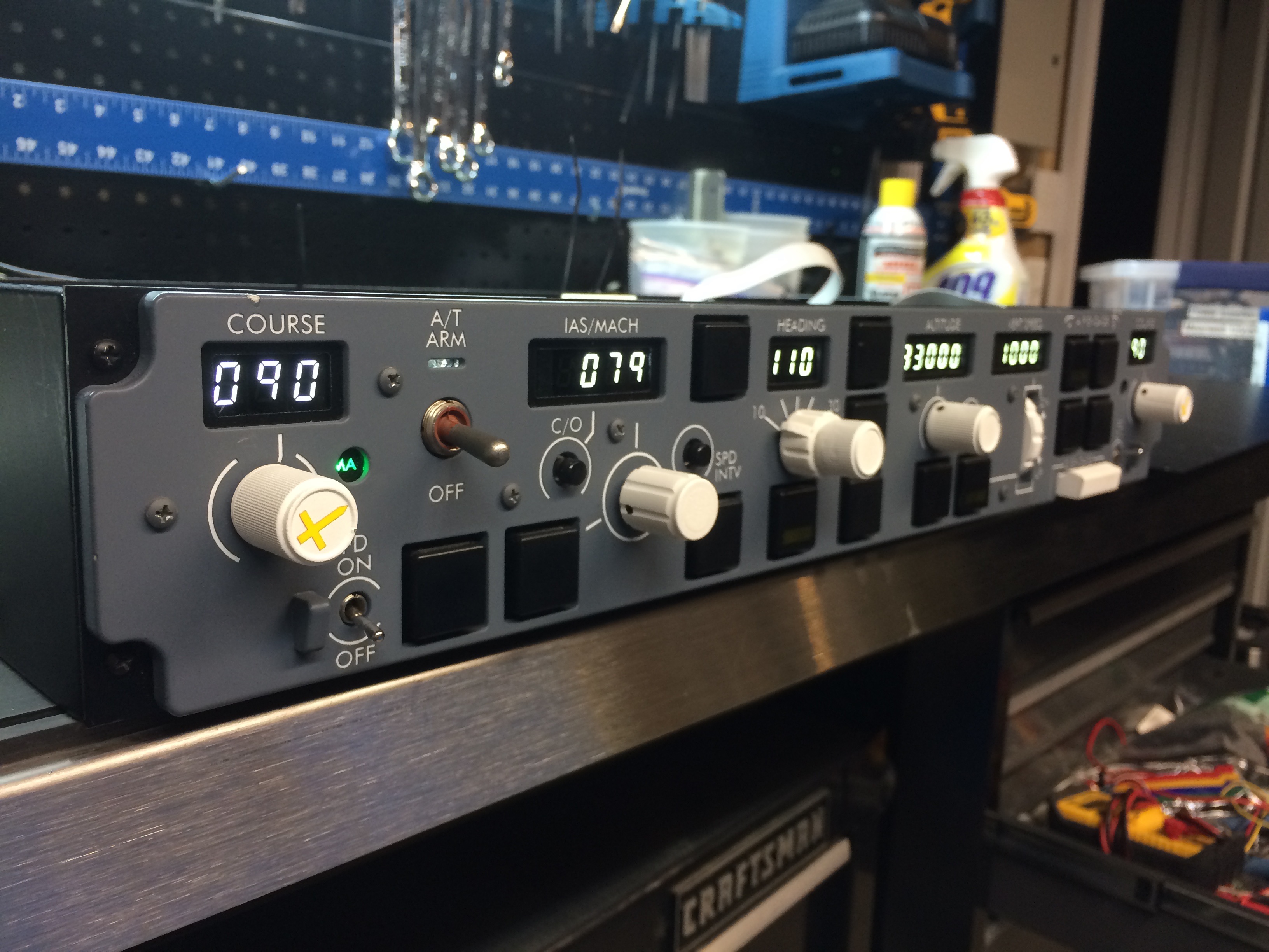
The FDS MCP/dual EFIS units are beautifully constructed, sturdy pieces that are faithful to the originals, with precise dimensions on the front faces. In spite of this, the units do not fit on to the Boeing mounts without significant modification. The original mounting brackets are relatively thick given the importance, weight and cantilevered configuration of the autopilot system in the real aircraft.

In order to fit the FDS units into the mounts, I cut openings in the sides of the FDS MCP. To take advantage of the Boeing angle brackets, I mounted two #10 nutplates on the inside of the MCP case to allow the mounts to be squeezed together and the screws attached, all without opening the MCP case. For this application I chose an aerospace fastener made by ClickBond, a brilliant, mil-spec system that allows the nutplates to be attached with a two part epoxy, thus avoiding riveting. I also drilled holes in the FDS shelf that holds the MCP and dual EFIS units. I used two large clamps to hold the assembly together while inserting screws from the bottom. Each screw went through the FDS shelf, then through the Boeing angle bracket, and finally into the nutplate mounted on the inside of the FDS MCP.
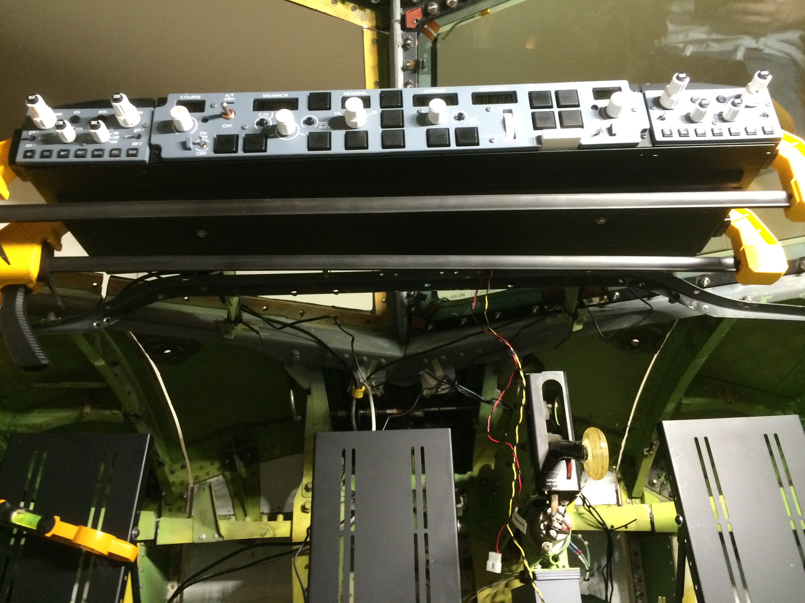
In each of the FDS EFIS units I mounted two additional floating nutplates, used to fix the units into proper position on the shelf. After mounting these units, I was able fit the FDS glare wings and glareshield and the result was a very clean install that looks great.
The MIP as originally received from FDS was assembled in their factory as a complete unit and fully wired, including the glareshield, MCP/dual EFIS units, MIP lower EICAS screen and FMS/CDU bay. It was also designed to be a freestanding unit, with easy access to the backside.
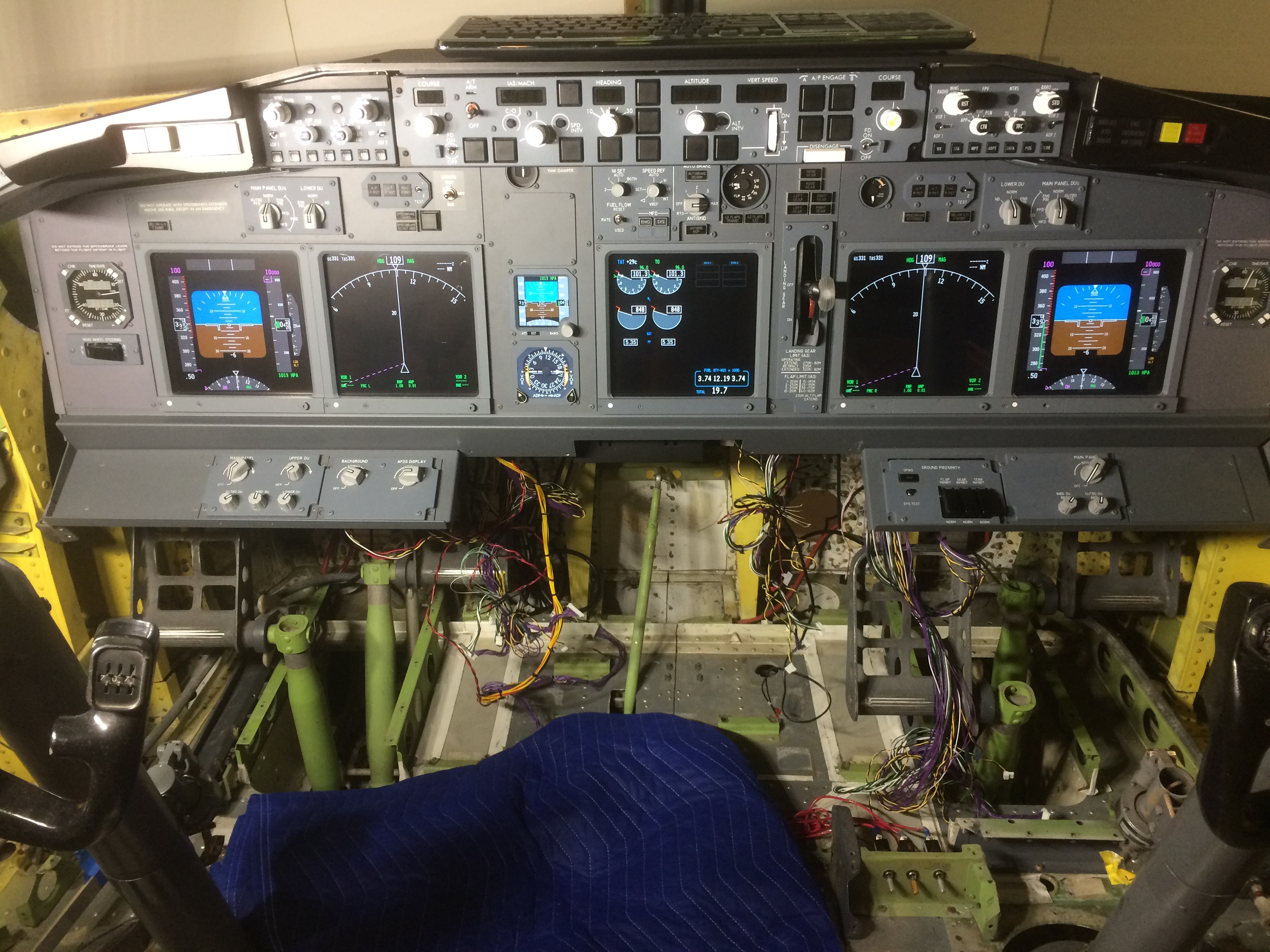
In order to be able to handle the MIP frame easily, I would need to strip all the avionics out. This required making the avionics much more modular than they came from the factory. I repurposed several AMP cannon plugs salvaged from the Boeing cockpit, splicing them into several large wire bundles connecting the various components. This allowed me to separate the glare wings from the MIP, and also to remove all of the MIP panels from the frame in groups of 3 or 4.
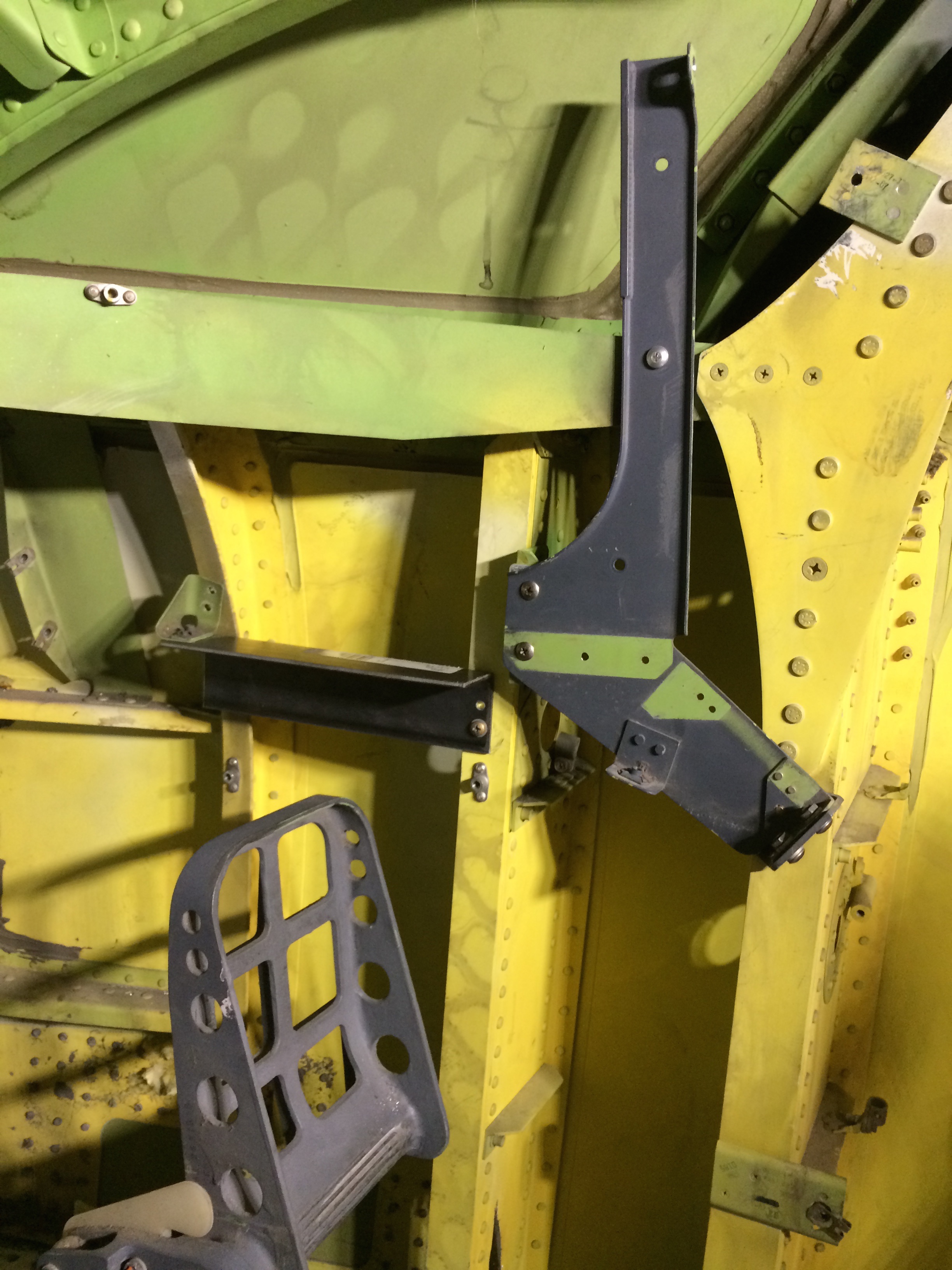
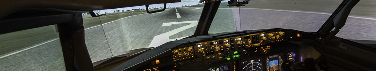
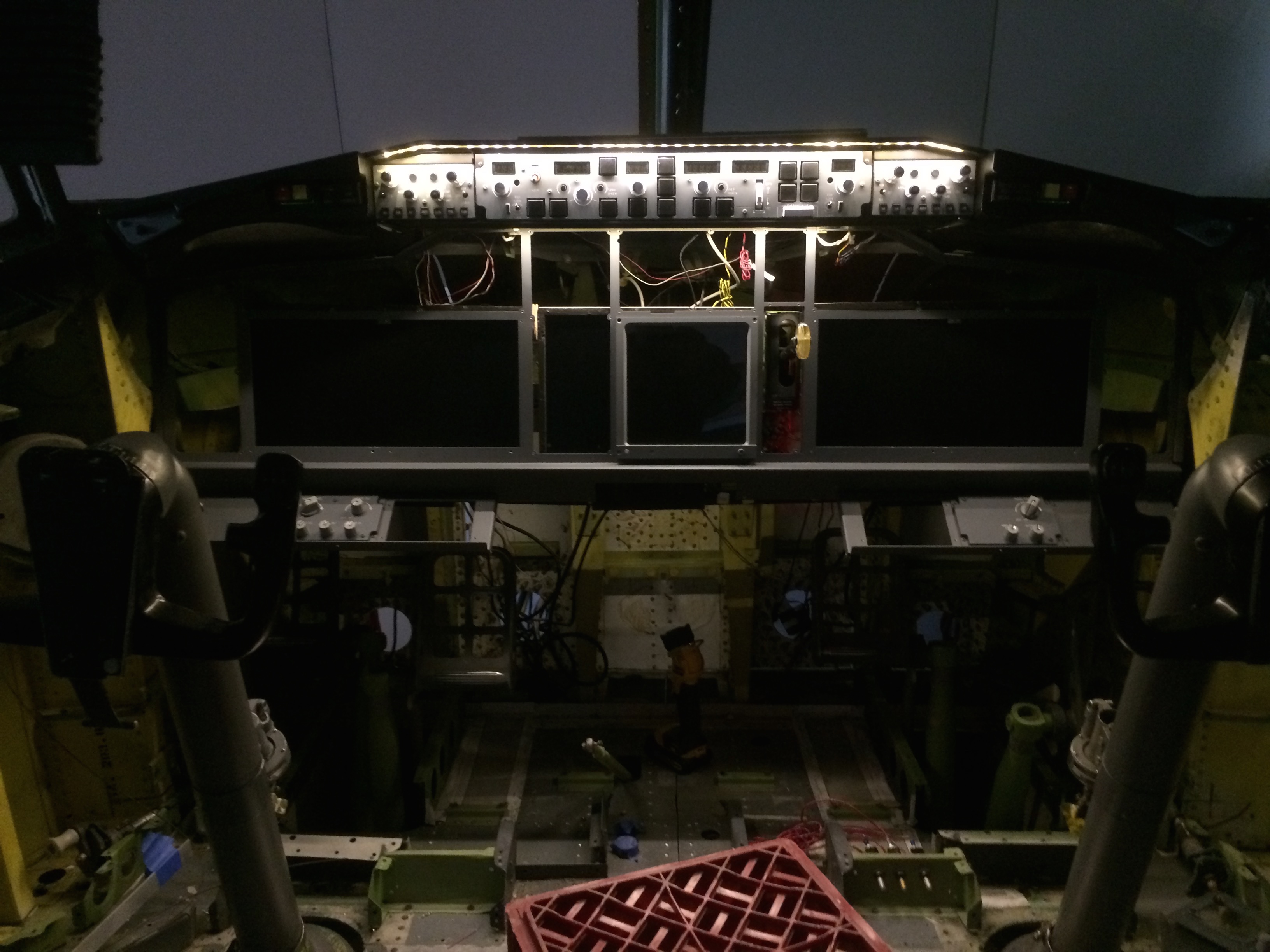
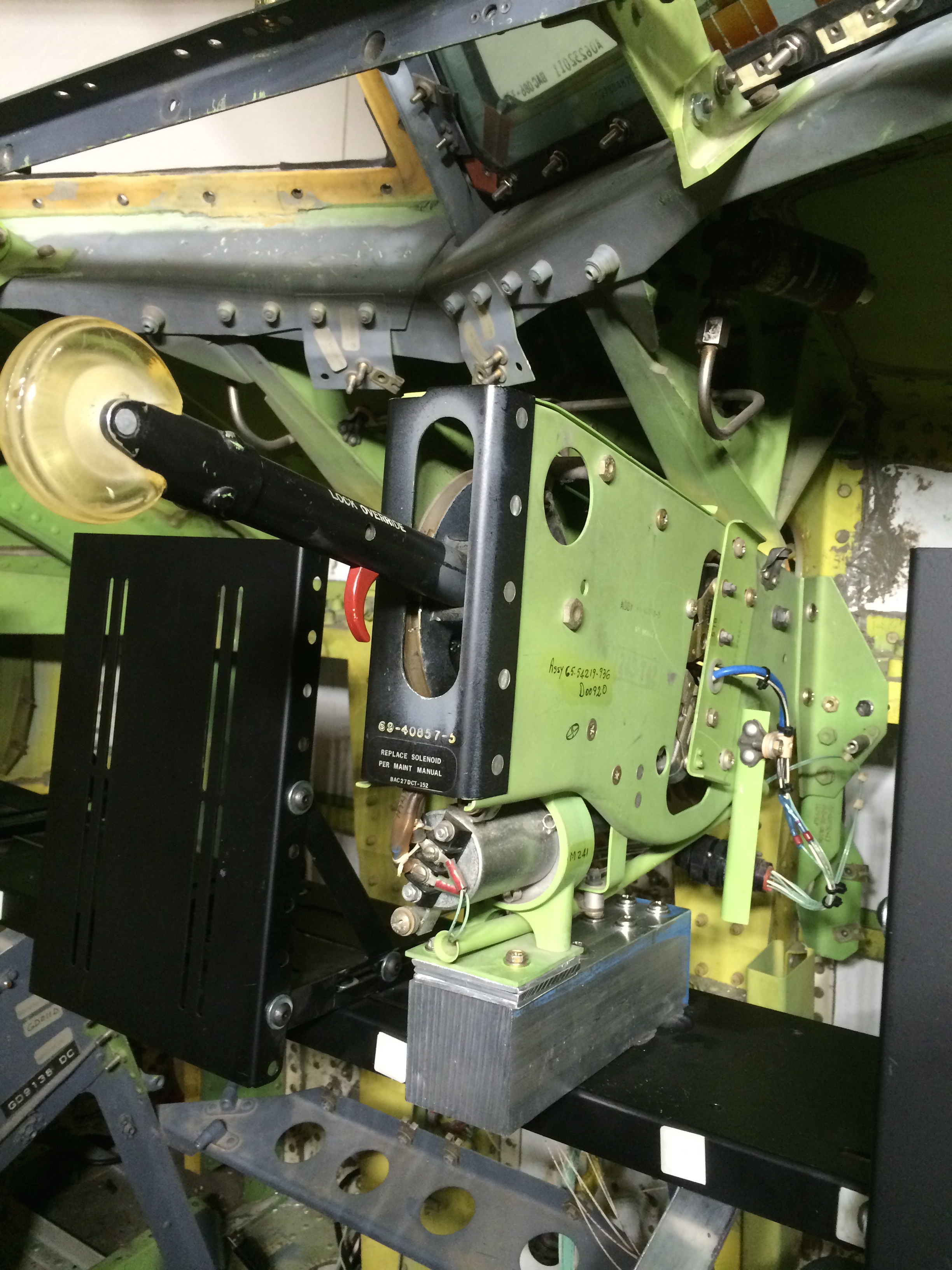
FDS uses a shelf that spans the full width of the MIP to support the monitors used for the displays. These are typical LCD computer monitors with their plastic cases removed. Fortunately this shelf was the exact width of the Boeing opening, so I simply needed to fabricate some brackets to hold the shelf onto the Boeing structure. I built an aluminum support for the Boeing landing gear lever to help support the FDS shelf.
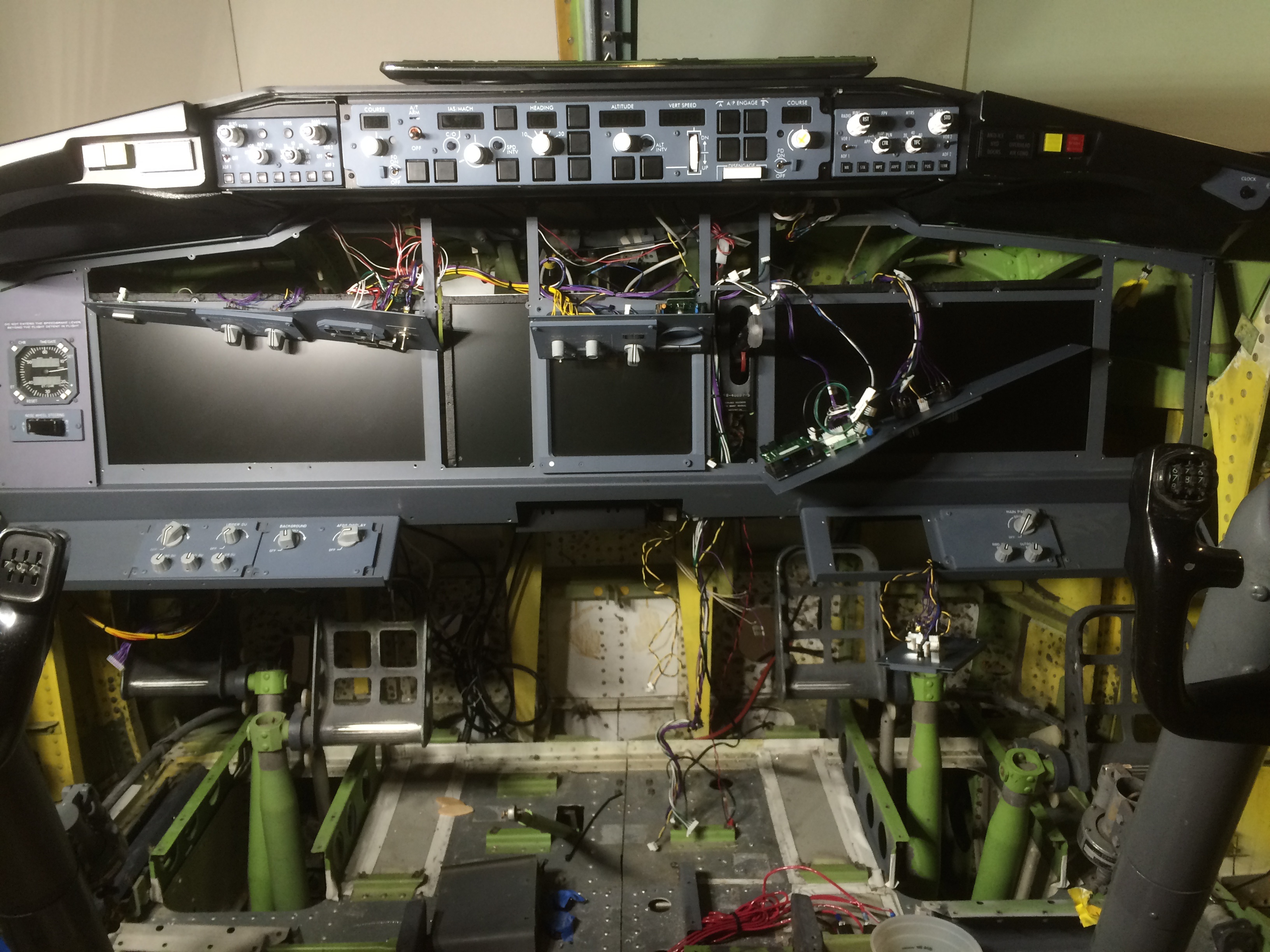
After mounting the shelf, I attached the monitors and started a cycle of repeatedly dry fitting the now bare FDS MIP frame to figure out the right angle for the monitors and the proper place in space for the MIP.