
In this post I will describe how I figured out the wiring diagram for a real Boeing 737 landing gear lever mechanism, including the solenoid and Korry lights.
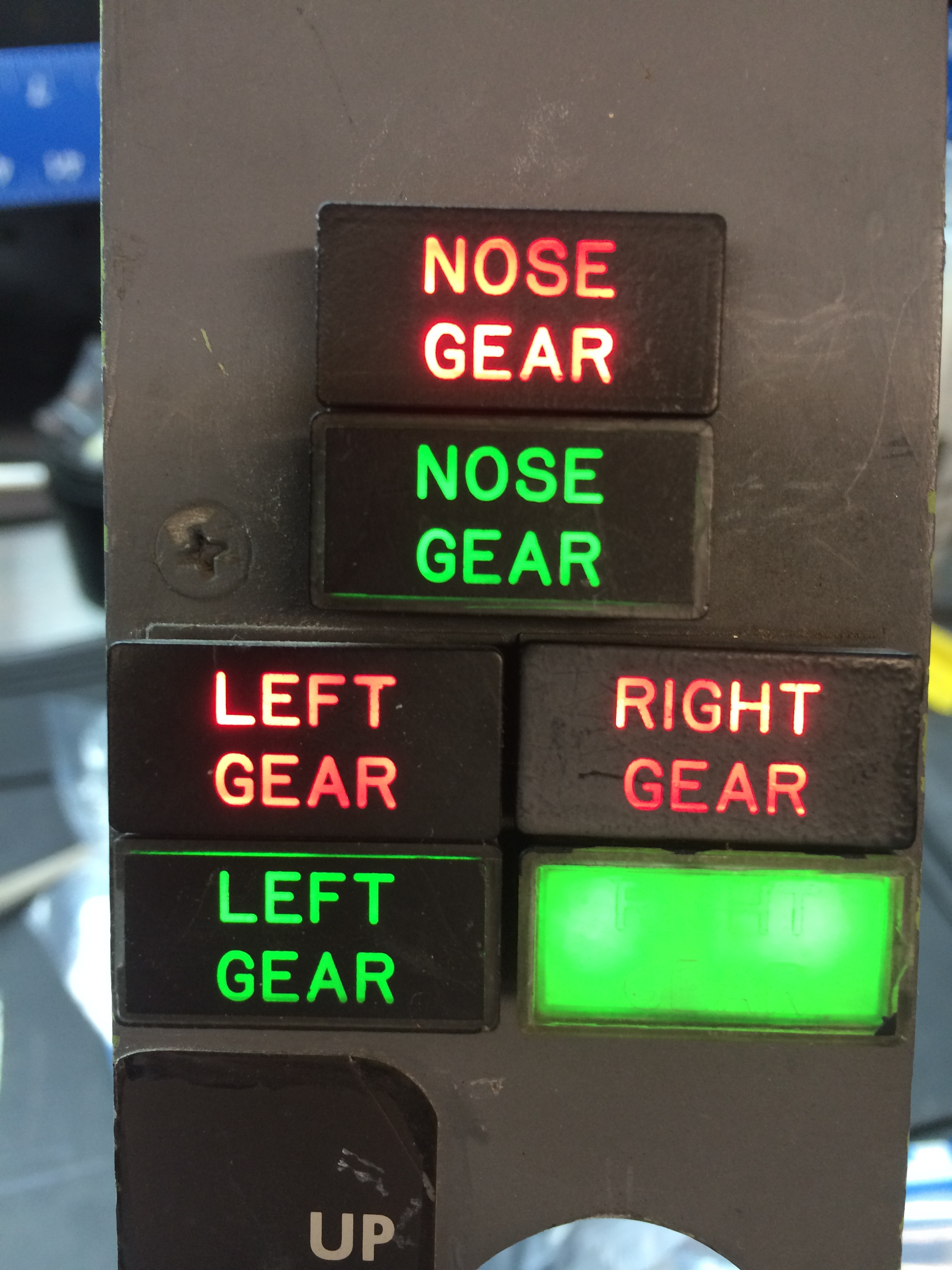
I’ve seen (and even owned) several landing gear levers that were designed and marketed for the home simulation market, but they just don’t have the heavy tactile feel of the real thing, and I’ve never seen any that have a working solenoid or override lever. The cockpit I bought fortunately still had the original gear lever still in place, complete with the six Korry annunciators that serve as gear position/transit lights.

The solenoid is a 28 volt device that, when energized, allows the lever to be pulled up to initiate a gear-up cycle. In the real aircraft, a number of logical conditions must be met for the solenoid to be activated, which prevents the gear from being raised while the aircraft is on the ground. The gear handle itself is equipped with an override trigger that allows to pilot to raise the handle in the event that the solenoid fails.

The solenoid wiring was easily determined as there were only two wires, one of which had to be 28 volt and the other a ground. The position switch wires were also easily traced back to the cannon plug. I was surprised on initially removing the assembly that only the gear down position had a switch installed. Although holes were present for mounting a gear up switch, the switch itself was missing. I can only assume that in the real aircraft the up position is read somewhere along the cable that runs to the actuator. For my simulator I just added an identical switch scavenged from another part of my project.
There are several manufacturers of annunciators for the home simulation market, but once again, there’s nothing quite like the real thing which have the press-to-test function available.
The wiring of the model 319 type 1 Korry annunciators have been described by David Allen. These are ground-seeking type circuits with 4 terminal lugs. Terminal 1 is the 28 volt input voltage. Ground terminal 2 to illuminate the indicator. Terminal 3 is grounded for a ‘test all’ function that lights the indicator, but extinguishes the light when pressed. Terminal 4 is grounded for a press-to-test function.
The wiring scheme is as follows:
24-pin cannon plug:
- Pin 3: common to all terminal 3’s (test all function)
- Pin 4: nose red terminal 2
- Pin 5: nose green terminal 2
- Pin 6: right red terminal 2
- Pin 7: left red terminal 2
- Pin 8: right green terminal 2
- Pin 9: left green terminal 2
- Pin 10: common to all terminal 4’s (press-to-test function)
- Pin 14: +28v to the reds
- Pin 16: +28v to the greens
- all other pins: unused
12-pin cannon plug:
- Pin 1: ground
- Pin 2: +28v
- Pins 4 and 5: gear up switch
- Pins 6 and 8: gear down switch
- all other pins: unused