Having overcome the major hurdle of implementing dynamic force feedback, I have been busy performing other tasks that will be most easily accomplished while the floor remains in vertical position. These include wiring the brakes and stick shakers, as well as rewiring the throttle quadrant with salvaged AMP cannon plugs that allows the interface cards to easily detach from the mechanical parts of the unit. I used a 55 pin plug for the switches and pots, and a separate plug with larger 16 gauge pins for the power connections.

I spent at least a week going over the underside, testing all the functions and tidying up cable runs. Once this section is put down into its final horizontal position, there will be only 20 inches between the flight deck and the floor of the basement, so I will still be able to get in and work on things, but it will be a lot less convenient and probably a lot more likely to induce neck and shoulder pain. Twenty inches seems like a lot, but that’s the distance from the flight deck to the floor, and there are a lot of mechanical parts in between, such that there won’t even be room for a creeper.

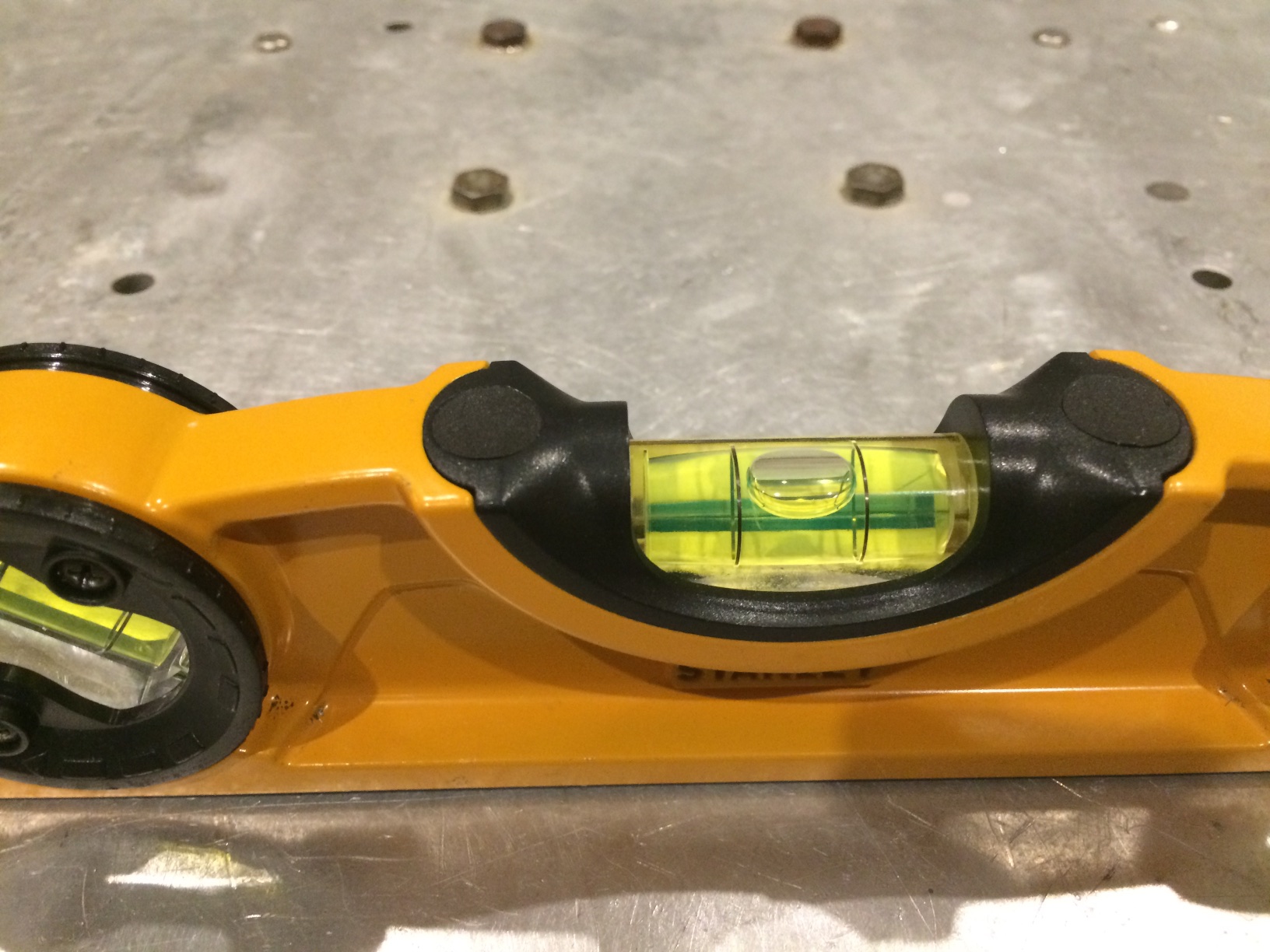
The day finally came, and after one final cleaning, I cut the heavy cable ties holding the floor section to the ceiling joists above, and started sliding the section as far forward as it would go in the room. I called my buddy Adrian, a senior F/O at jetBlue, to come over and help me lower it. I figured it would be pretty easy for two of us to lower it down, as it seemed to me that most of the weight was concentrated in the yoke and rudder mechanisms located fairly far forward. It wasn’t that hard, but the aft end was quite a bit heavier than I thought. Luckily Adrian’s fiancee Kelly, herself a Captain and check airman at Frontier, was there to help place the aft floor supports, which I had made from short sections of 6×6 and 2×6. Once we got it down, a quick check revealed that the flight deck was perfectly level in all directions. Looks like my cuts and indexing were precise enough!