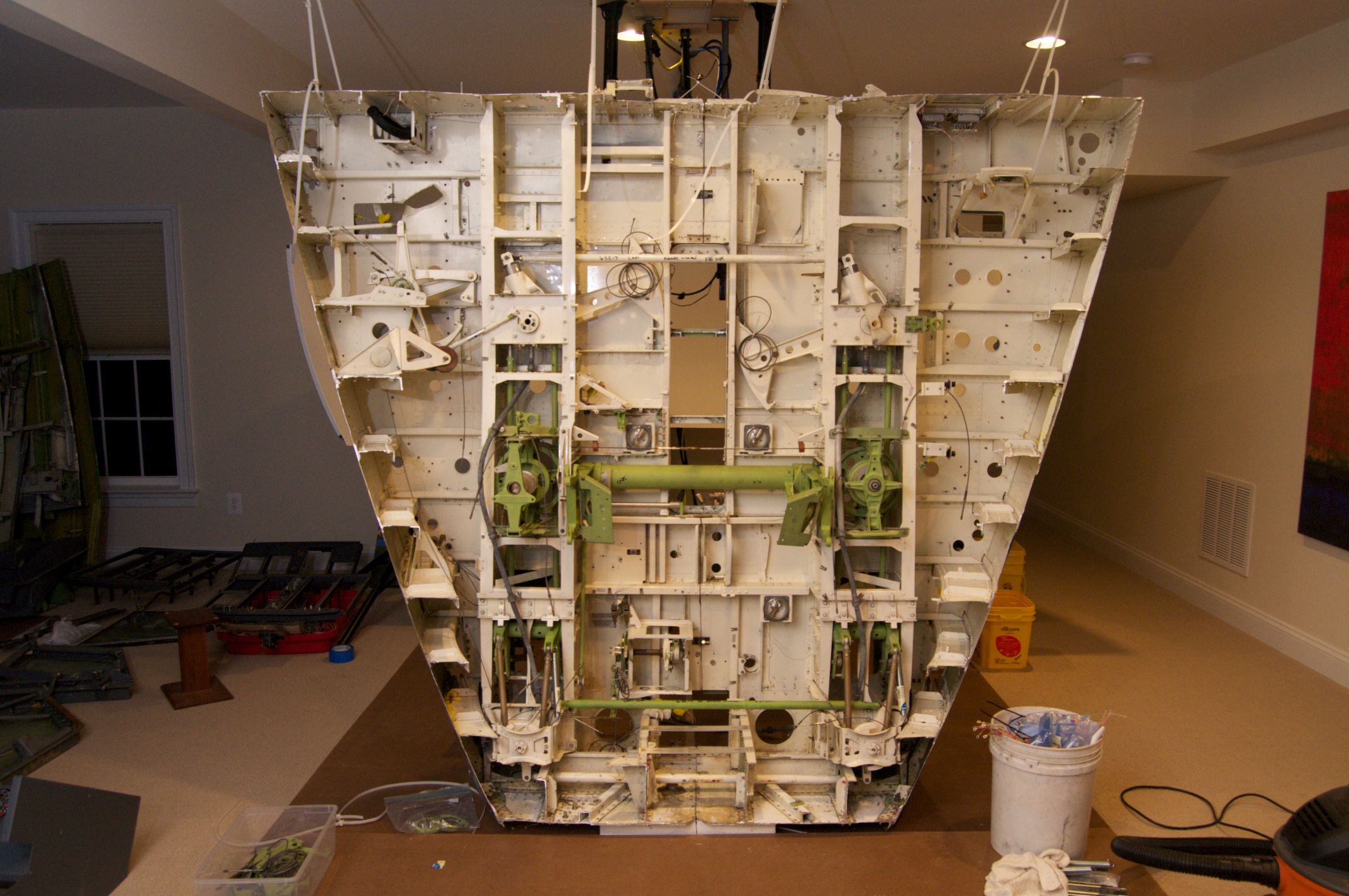
After reinstalling the exterior door into the basement and securing the forward floor section to the ceiling, I re-joined the two halves by mounting more of my custom fabricated brackets onto various structural ribs. I had pre-drilled the holes for these brackets using cleco fasteners while the section was still in one piece in the driveway. I discovered early on that the metal fabricator who made the brackets did not punch the holes in identical positions, so each bracket had to be marked in order to match up to a specific location later on.
The throttle quadrant and radio pedestal sit on a large sturdy bracket that covers the big hole in the middle of this section. Luckily for me this bracket also crossed the centerline and was easily removable. Replacing the bracket added a great deal of structural stability to the reassembled floor section.
The next step was to reinstall the flight controls. The rudders and brakes were easily reconnected with control rods and hardware, and the roll axis was re-linked by connecting the threaded control cables.
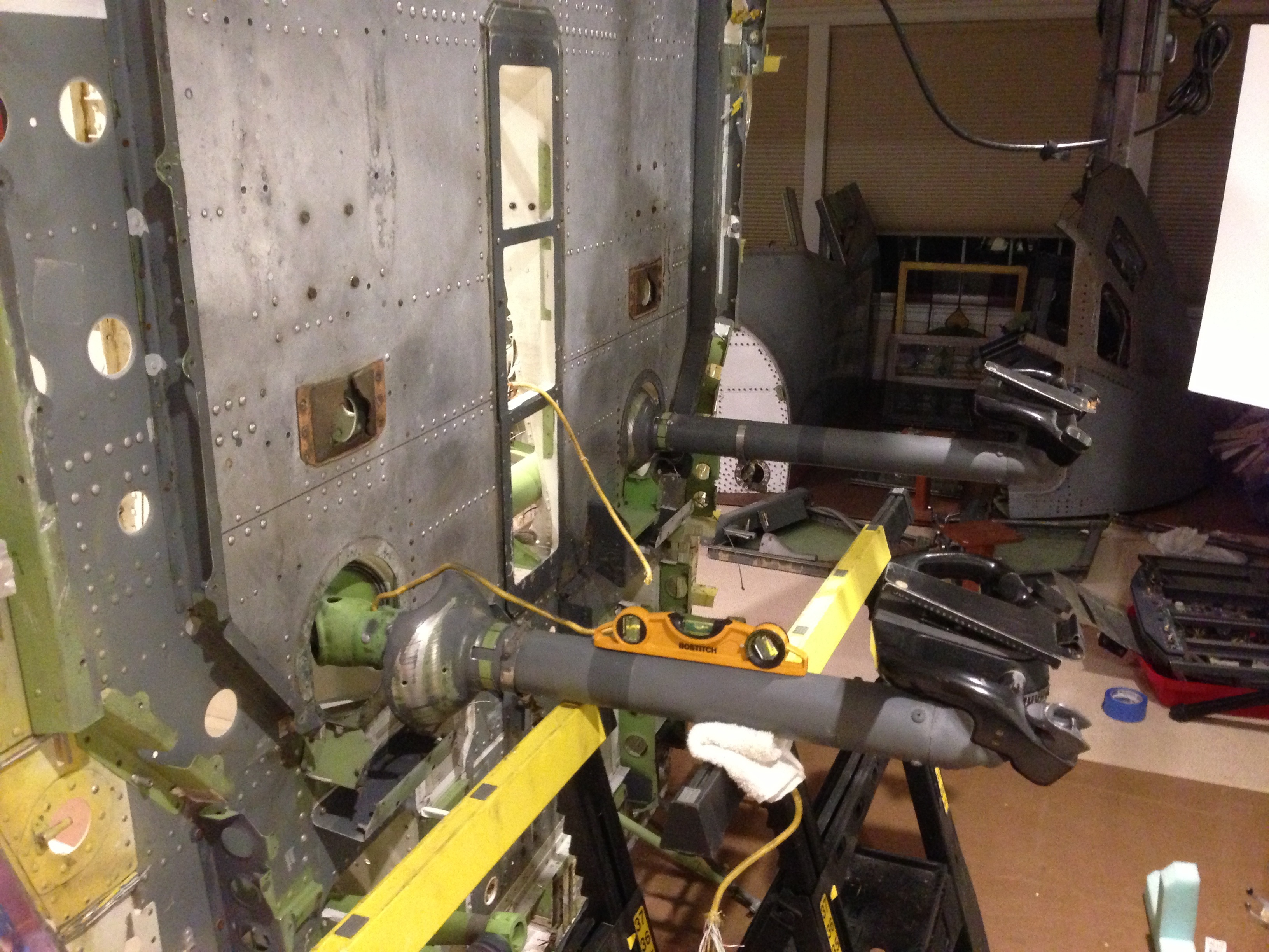
Reinstalling the control yokes proved a bit more challenging as they are connected to the pitch crossover tube, a large heavy piece with a three inch beveled gear on each end. I had neglected to index the columns in any way, so when reinstalling I used two adjustable sawhorses and a bubble level to make sure that each yoke was indexed to the same position.