Restoration and installation of cockpit trim

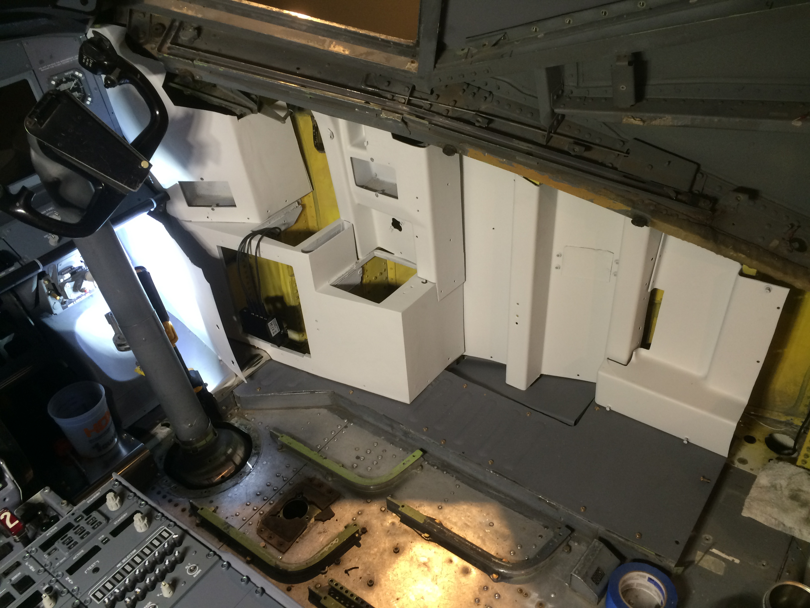
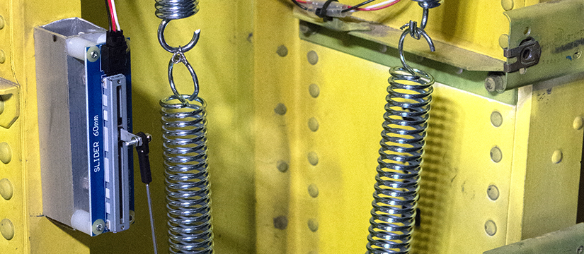
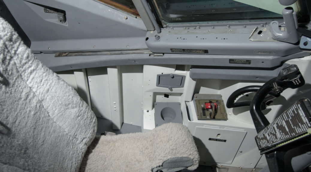
Having finished the bulk of the avionics work, it was time to focus on installing the various trim pieces, mostly plastic, that finish off the cockpit. In order to have the maximum amount of working room, I decided to complete most of this task prior to installing seats and the circuit breaker structures that make up the back wall of the cockpit.

Captain side trim nearing completion. P2 and P3 windows are installed. Oxygen mask box, cupholder and ashtray are all painted gray.

My cockpit sat in the boneyard for about two years before I bought it on eBay in 2011. All of the cockpit windows were certainly removed early on, because they are very expensive parts and the market for serviceable used units is robust. The result of this was that the remaining parts of my cockpit were exposed to the elements for the three year interval after the airplane landed there after a brief flight from Chicago in 2008. The dust and rain that entered the cockpit caused a number of the fasteners holding the trim in place to become seriously stuck. Once again PB penetrating catalyst came to the rescue, but not all of the fasteners were easily removed. Many required turning with locking pliers (eg vice-grips), and the most stubborn ones required drilling out.  Just removing the trim took several months back when the airplane was still in the hangar.

The cockpit in 2012, after the circuit breaker walls were removed and the tedious task of trim removal was starting.

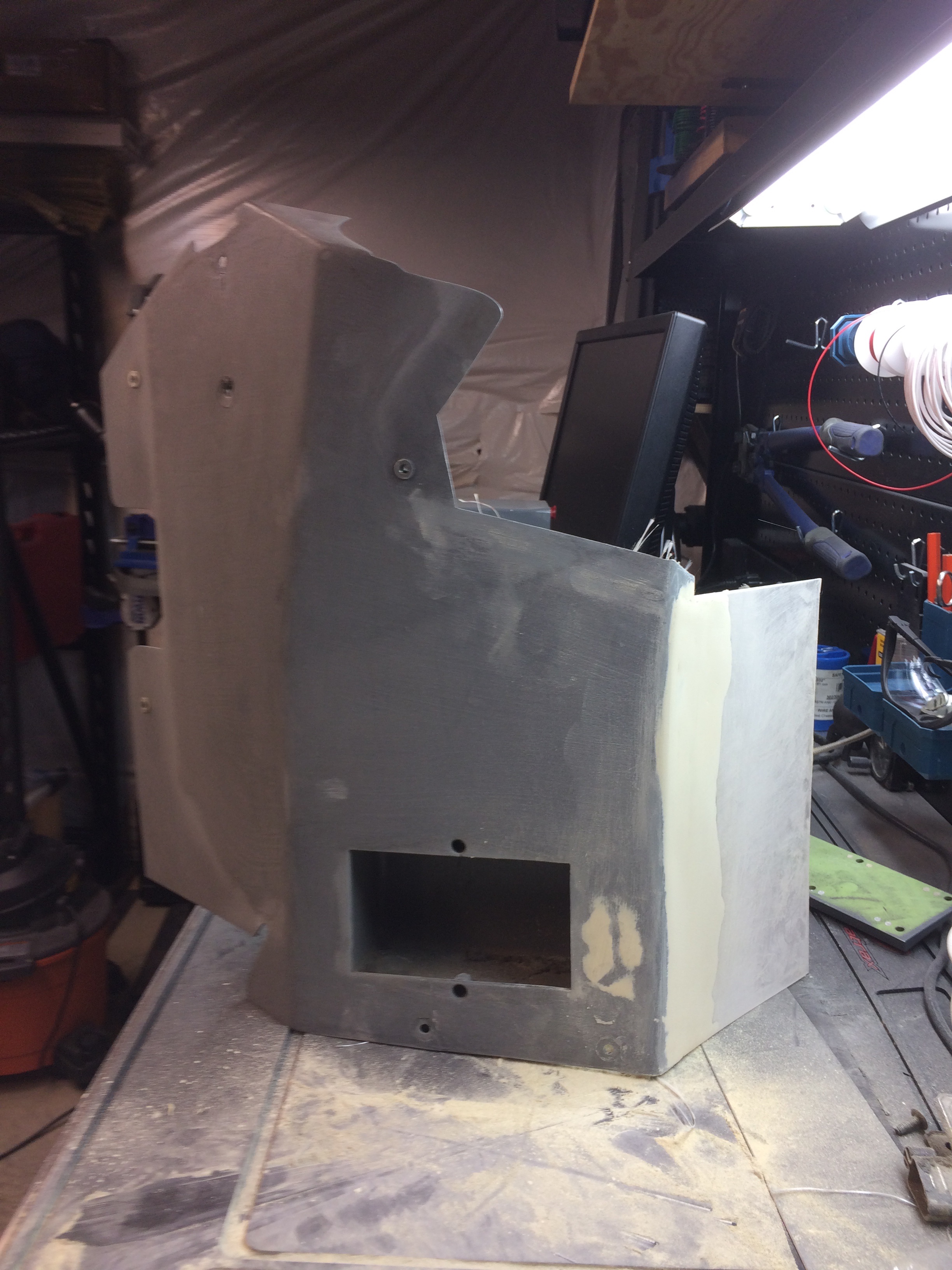
As this trim was 25 years old, many of the plastic pieces were very brittle, and some pieces were unavoidably damaged during removal. Several broken pieces needed mending, which I did by backing the pieces with fiberglass, then filling in the cracks with 3M flowable finishing glaze and sanding before painting.

FO side trim piece during restoration. Beige spots are 3M flowable finish glaze after sanding. Open space at the bottom is for factory original ashtray.

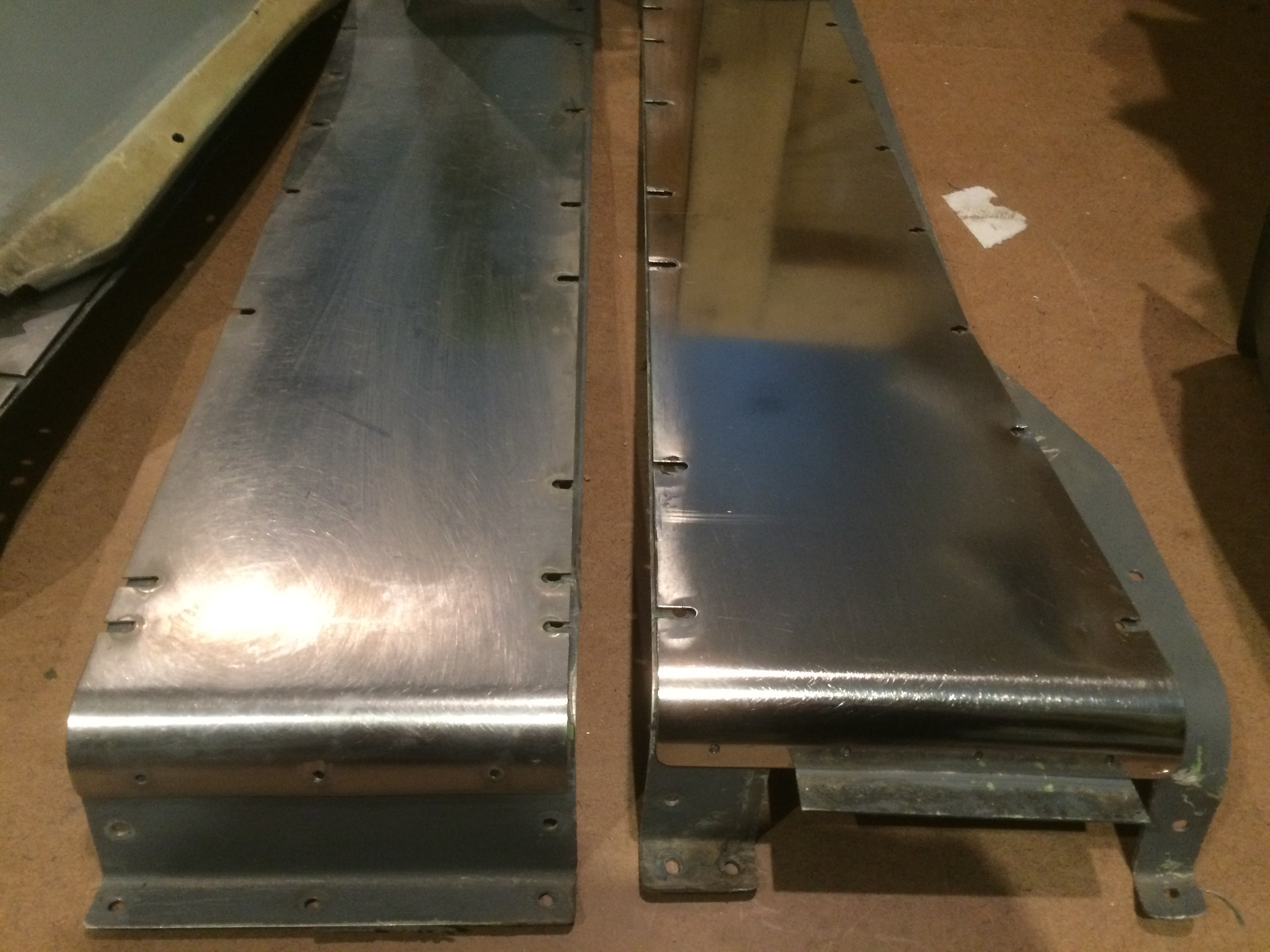
The only unpainted metal parts were the rudder skids, which were easily polished with an orbital buffer and some 3M rubbing compound.  The corrugated metal floor pieces outboard of the seat J-rails were stripped and painted.

Rudder pedal skids before and after restoration. This is where the pilots rest their heels when their feet are on the rudder pedals. Boeing must have given up painting these because they get so much wear. Easy to get a mirror finish with a little 3M rubbing compound and an electric buffing tool.

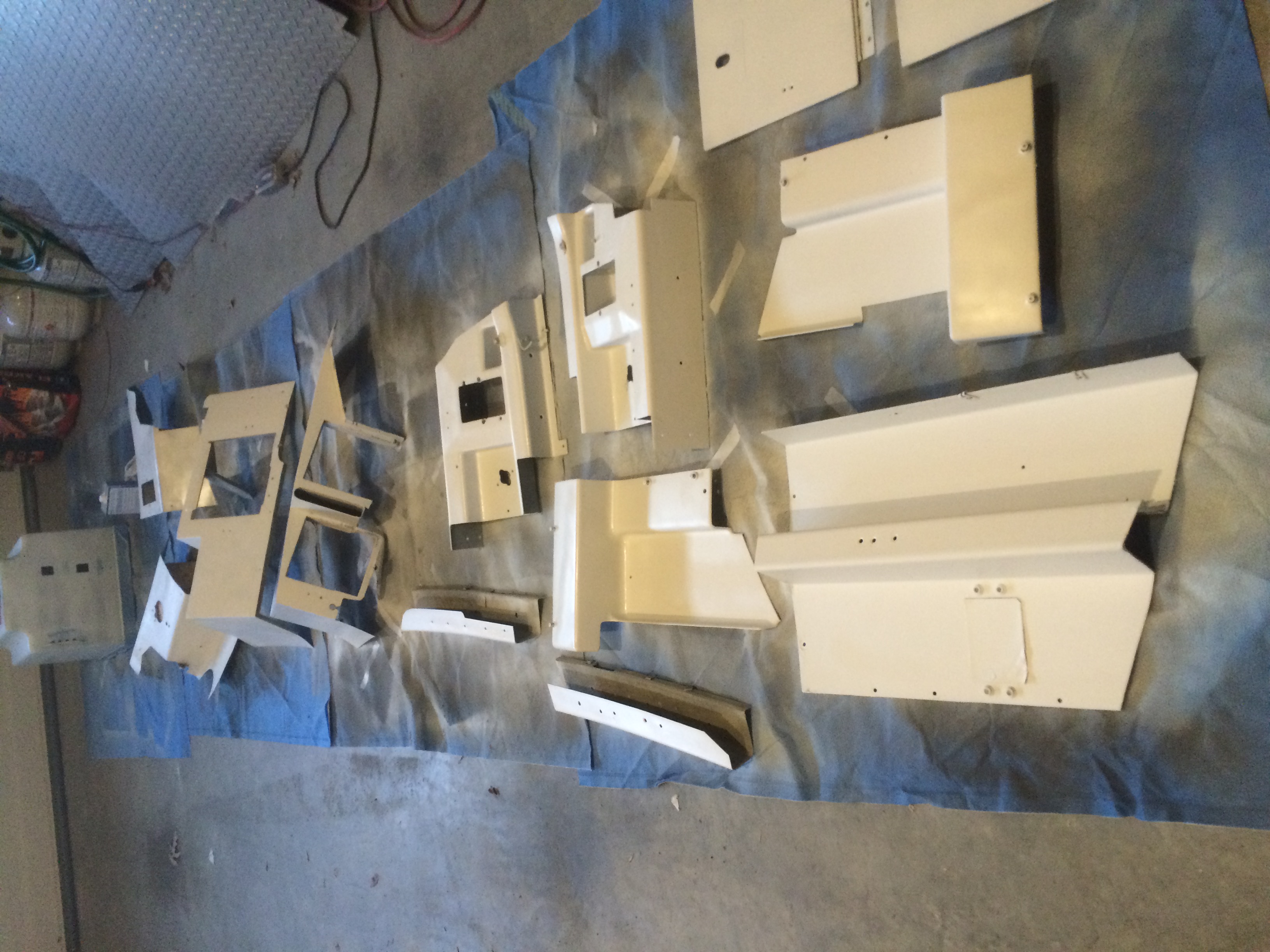
The trim pieces as well as the screw heads were painted according to location. My cockpit is a classic 737 model, but I was building a 737 NG model, so I painted the lower parts of the trim in a light gray primer obtained at Home Depot. The upper pieces were painted in a medium gray primer. After applying two coats, I applied a clear matte finish on top of each of these to eliminate the sandpaper texture of the primer.

Off white paint for the lower sections of trim. The pieces themselves are pure classic 737, but the paint color lends the illusion of an NG model cockpit.


P2 windows and associated trim pieces after painting with medium gray.

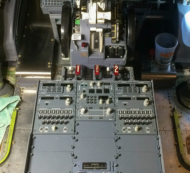
The reassembly process was a bit of a jigsaw puzzle, made easier by the mounting points left behind on the OEM shell. The basic installation scheme is to start low and aft and work your way forward and to the top, as many of the pieces overlap in a specific configuration. Straight awls are helpful for lining up holes to the nutplates. After the trim pieces were installed, various accessories were installed on top, including cupholders, oxygen mask storage boxes, and ashtrays. Believe it or not, when this airplane came off the assembly line in 1988 the cockpit was equipped with ashtrays. Of course this is now a non-smoking cockpit.  At some point in the future I will replace the ashtrays with custom sheet metal pieces  with USB connections to each of the computers running the simulation, but until then the original (very clean) ashtrays remain in their positions.

FO side trim during installation. Light gray piece at upper left needed extensive repair, shown in photo above.

Installing the avionics pedestal

One of the last major avionics projects prior to closing up the cockpit with trim was the installation of the avionics pedestal. This piece is screwed to the floor and has Dzus rails for mounting various avionics including the radio control heads.

Boeing OEM pedestal prior to removal. Note the entire structure was removed prior to tackling this part of the project, given how stuck the fasteners were. Throttle quadrant and flight control removal was delayed until even later, when the floor was in vertical position.

The pedestal itself is a Boeing OEM unit that was installed in the cockpit I originally bought in 2011. Removing the pedestal required a great deal of patience as the screws holding it in place were exposed to the elements for a couple of years while the cockpit was waiting in the boneyard for me to rescue it. PB penetrating catalyst was essential to this task. I stripped the pedestal and refinished it with a self-levelling compound made by 3M. I then painted the unit in the style of an NG model 737, with off white for the body and gray trim around the top. Clear matte spray finish makes for a better appearance and covers up the sandpaper texture of the primer.

Pedestal mount, looking forward. Gray structure at the top is the base of the throttle quadrant. Gray frame in the center of the picture is the pedestal base. As this piece crosses the midline, it was used to index the left and right sides of the floor during reassembly.

The power and USB cables were previously run under the floor back when it was still in vertical position. I chose a combo 12v/5v power supply to provide 12v to the FDS-SYS3 card and 5v for the lighting. This power supply also wound up being used for two USB hubs that wound up inside the pedestal. The backlighting is on a FDS-IBL-DIST-DIM with a FDS-IBL-DIST-EXP card. A 24v power supply was added later when I finished interfacing an OEM fire panel.

Pedestal during installation. Top of frame shows aft part of throttle quadrant and fire panel. FDS-SYS3 interface card mounted on wall on the left, USB hub on the top right. Small interface boards on either side are FDS-IBL-DIST-DIM boards. Avionics modules will be installed on Dzus rails.

After screwing the pedestal back onto the OEM nutplates, I connected the various pedestal modules one at a time. My pedestal has 2x multicom units, 2x NAV radio heads, 2x dummy audio panels, one transponder control, a cargo fire panel, a dummy radar control panel, aileron/rudder trim panel, a door access panel, and a lighting control panel.

Avionics pedestal complete after installation of modules, all manufactured for the simulation market by Flightdeck Solutions except the fire panel seen at the top.

Interfacing a Captain’s nose wheel steering tiller

Nose wheel tiller interface. Gray and black components at the top are Boeing OEM. Cables were cut, loop ends installed, and heavy duty springs fitted with bottom ends attached to cockpit floor. Intreface via Phidgets 60mm sliding potentiometer.

Having finished the bulk of the avionics installation, it was time to think about installing the plastic trim pieces in the cockpit. Before proceeding with trim installation, I had a few remaining tasks. In this post I will describe how I interfaced a Boeing OEM nose tiller.

When I purchased my cockpit in 2011, the complete nose wheel tiller mechanism was present. It worked fine, but was in need of cosmetic improvements. I was looking for a way to refinish the wheel itself, which is covered with a very thick, chip resistant coating, when a new-old-stock (NOS) OEM unit came up for sale on eBay…$79.50 plus shipping.

Since the initial design of the Boeing 737, nose wheel steering on the ground has been augmented by a metal control wheel just to left of the Captain’s thigh. On the ground, the airplane can be steered by differential thrust on the engines, but for fine control, especially at low speeds, the steering tiller is used to direct the nose wheel. Larger Boeing aircraft have this control duplicated for the FO, but in the 737, only one tiller is installed on the Captain’s side. In the actual aircraft, the tiller mechanism is connected to the rudder pedal linkage under the flight deck floor via steel cables. In the interest of time I elected to implement my steering tiller as an independent unit.

Detail of nose wheel tiller interface. Phidgets 60mm sliding potentiometer is connected to the lower aft spring using an RC control rod and safety wire.

I simply cut the steel cables and fitted the ends with heavy duty springs. A short piece of RC modeling rod is used to connect one spring to a Phidgets 60mm sliding potentiometer. This pot is then connected to a joystick card (eg Leo Bodnar BU0836X) and the axis is calibrated in FSUIPC. The video below shows how the RC rod is connected to the part of the spring with an amount of travel that is appropriate to the pot.