Completing avionics installation

Just after completion of installation of Boeing OEM TQ and pedestal. TQ was heavily modified by Art May-Alyea at Northern Fligth Sim, with custom interfacing to provide functionality. Pedestal components by FDS, except the fire panel, which is Boeing OEM.
Just after completion of installation of Boeing OEM TQ and pedestal. TQ was heavily modified by Art May-Alyea at Northern Flight Sim, with custom interfacing to provide functionality. Pedestal components by FDS, except the fire panel, which is Boeing OEM.


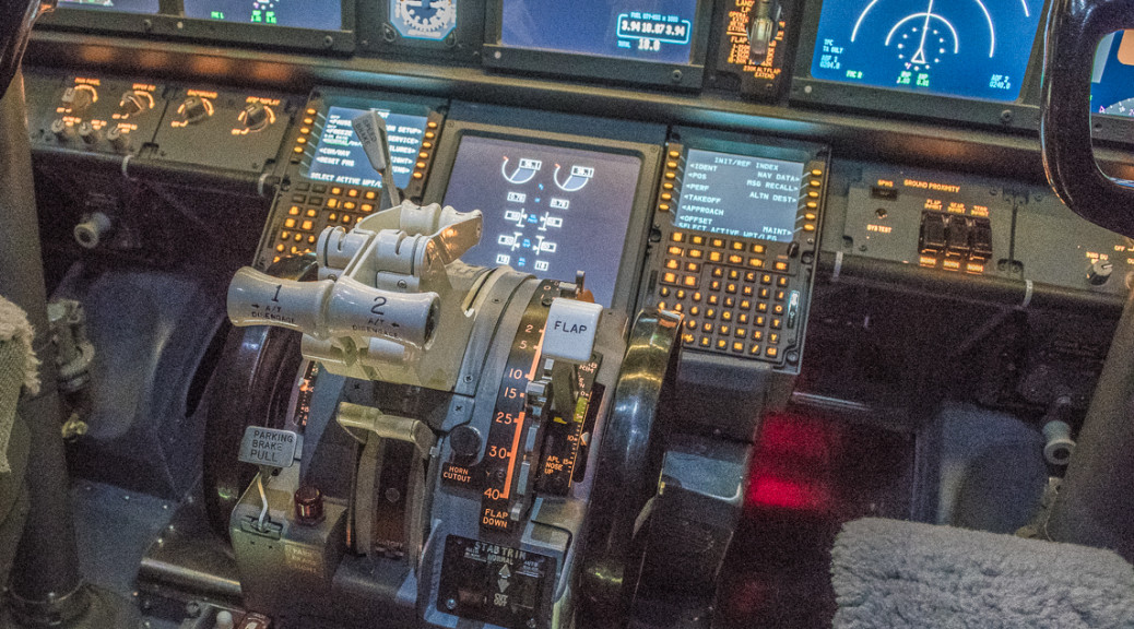
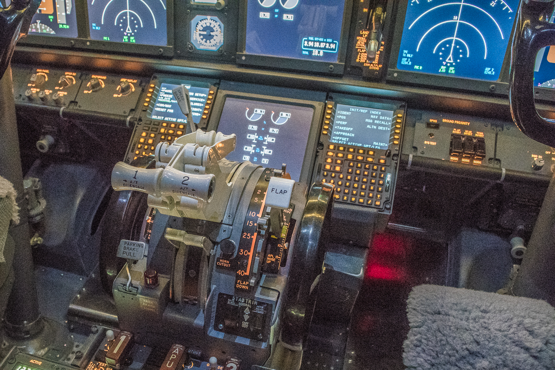
Having finished the modification of the FMS/CDU bay, I continued my top-to-bottom avionics installation. One of the most critical components, the Boeing throttle quadrant, is located just aft of the FMS/CDU bay.

The TQ I have was purchased several years ago from Art May-Alyea at Northern Flight Sim. Art has a wealth of experience converting old TQs from classic models to closely resemble those used in the NG. He completely disassembles the units, refinishes and paints all the components, installs microswitches to detect every switch position including every detent on the flap lever, then fits the assembly with motors for the trim wheels and throttle levers, as well as servos for the speed brake lever and trim indicator.

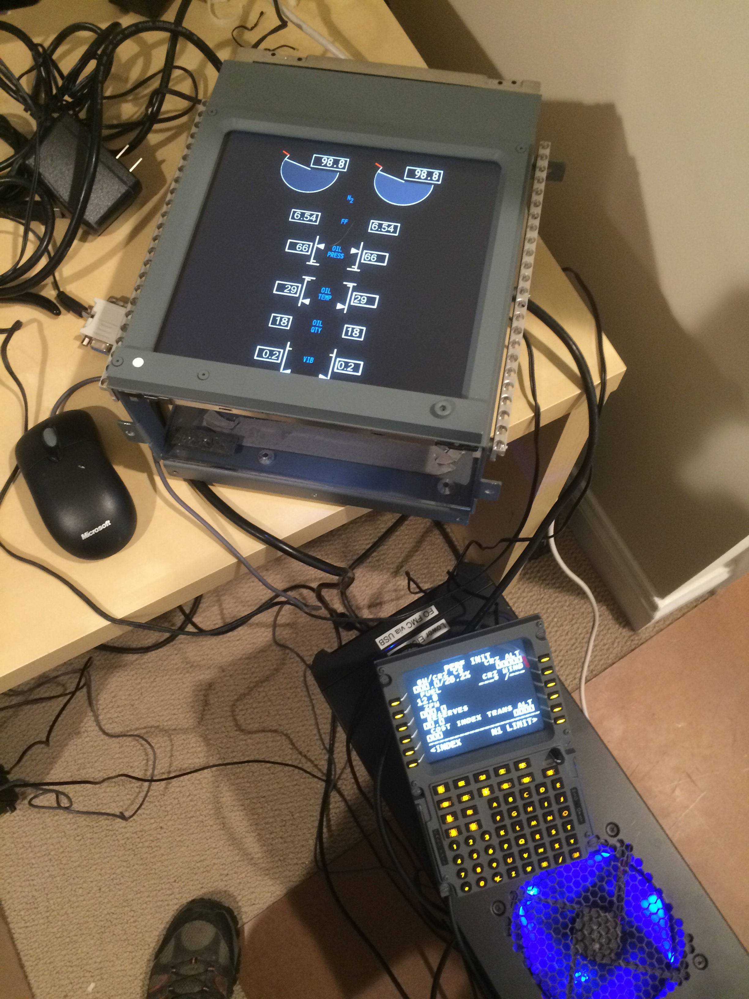
Art supplies the TQ conversion with bare wires coming out the front, and interfacing is up to the user. Full details of how I chose to complete the interface will be described in a later post, but the short version of the story is that most of the TQ is connected to a BU0836X joystick controller card from Leo Bodnar. The 12v motor driving the trim wheels are connected to  a PhidgetsMotorControl HC card. The throttle levers are driven by two 12v motors fitted with slip clutches and interfaced to two Pololu Jrk 12v12 cards.

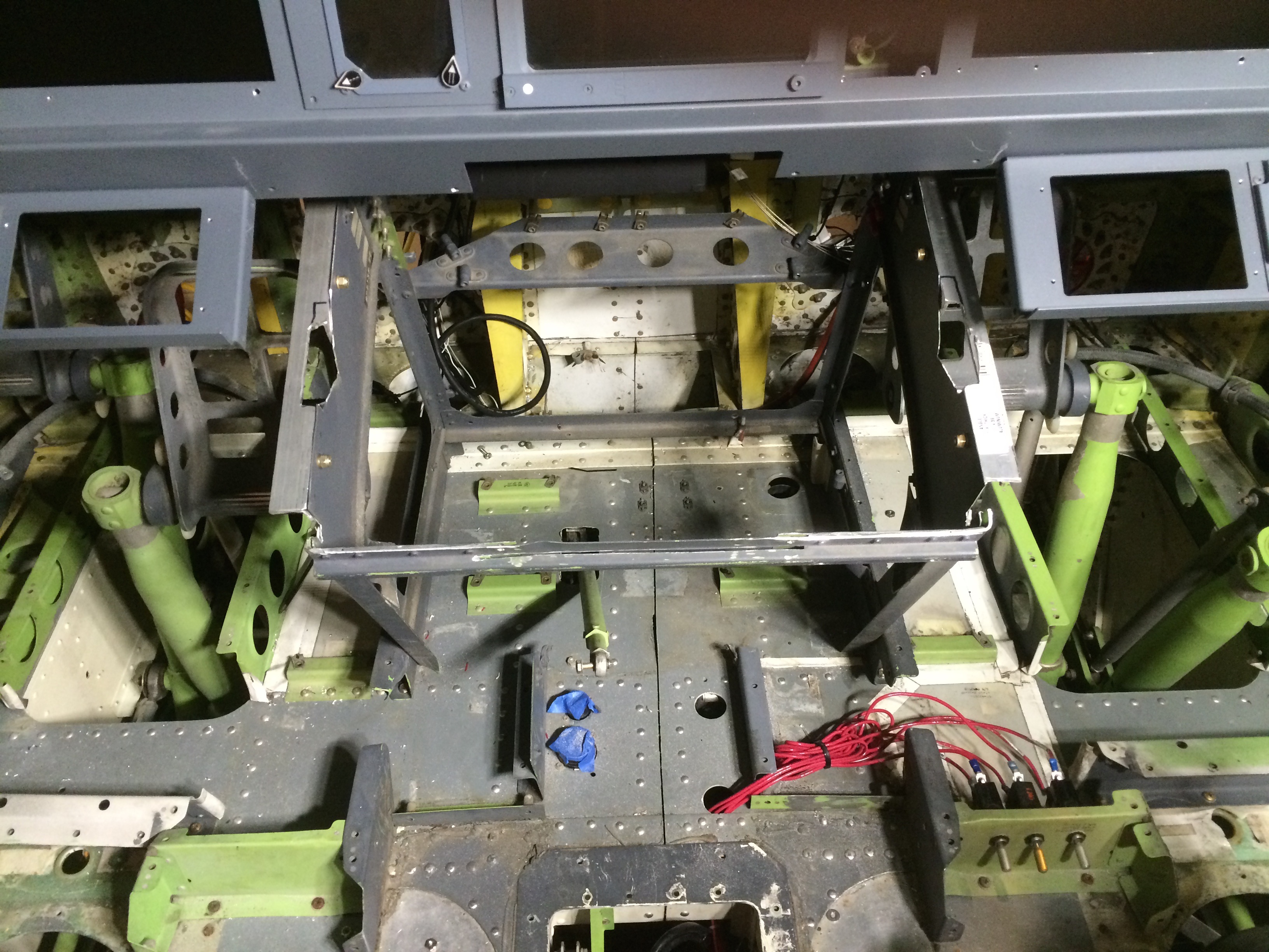
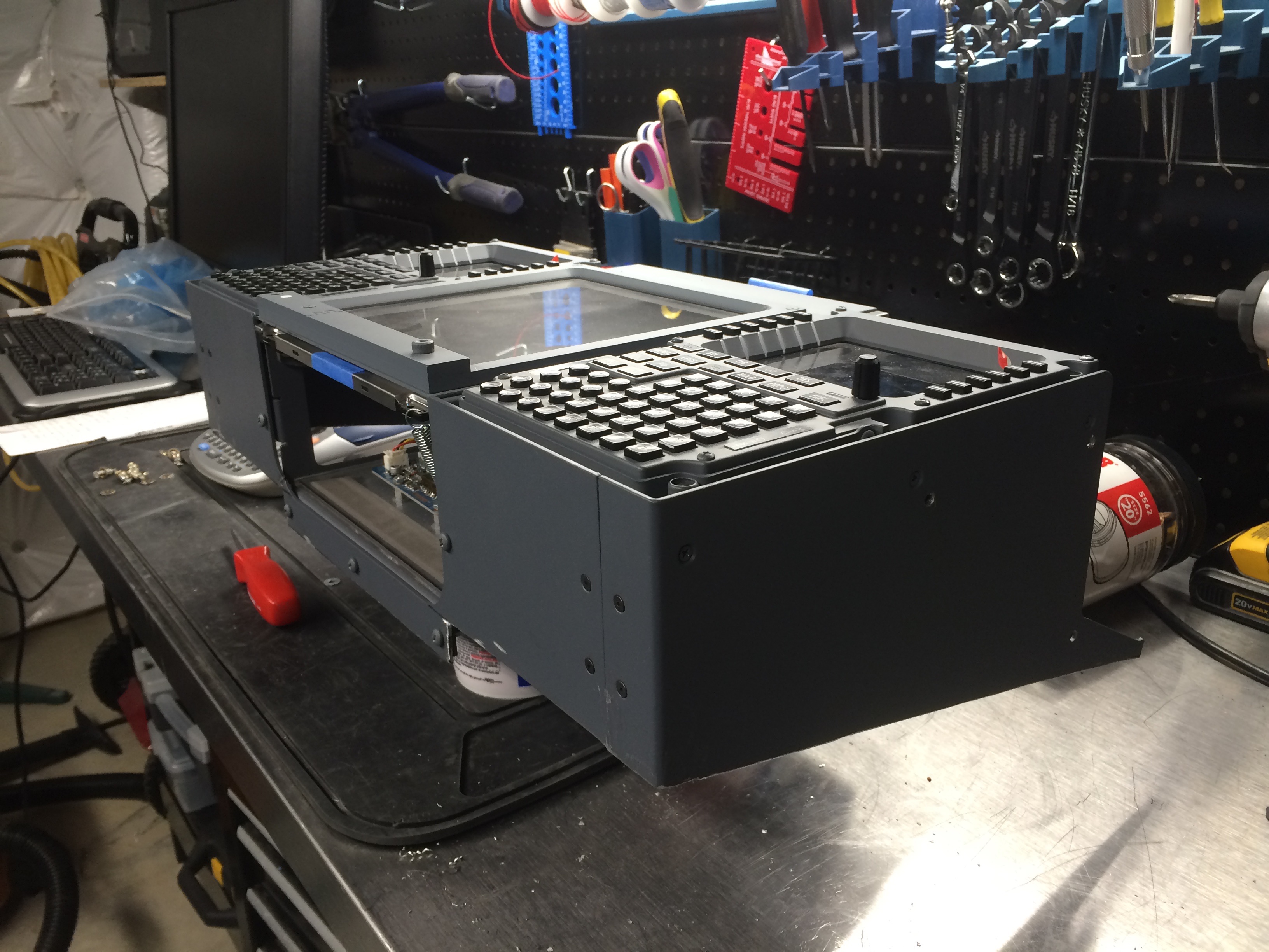
The pedestal itself is a Boeing OEM unit that came with the full cockpit I purchased from eBay in 2010. The frame  was removed, fully stripped, restored  and repainted in the colors of a typical NG model prior to reinstallation. All of the radios and other avionics in the pedestal were provided by FDS, and are purpose built for the simulation market. The one exception is the fire panel in the most forward part of the pedestal frame: this is a Boeing OEM unit that I reverse engineered and will describe in a future post.

Avionics installation in progress. Overhead, MIP and FMS/CDU bay essentially complete. Preparing to install TQ. FO seat installed temporarily to have a place to sit while performing avionics testing. Milk crates used as computer monitor and keyboard stands.


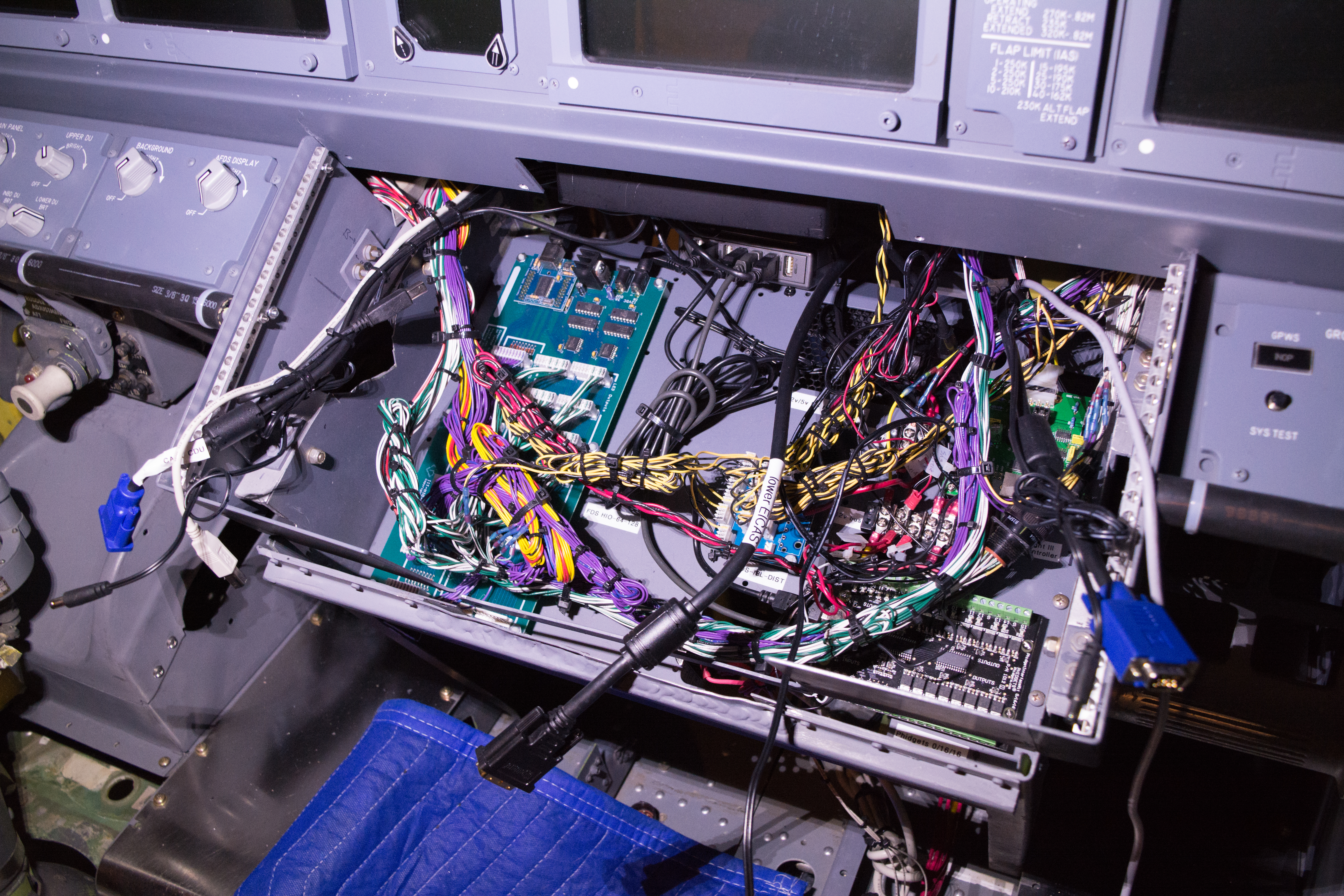
Prior to proceeding with installation of the trim pieces and back wall, I spent several months checking avionics functionality to determine whether I would need to run any additional wires behind any of the panels. Access to the back of the overhead panels is fairly easy thanks to FDS mimicking the OEM design . I didn’t think of everything, but I got most of the major kinks worked out prior to proceeding with the finish work.

FDS forward overhead panel viewed from the forward position. Boeing OEM mount allows the panel to swing down for maintenance access by turning two Camloc fasteners. FDS-SYS1X interface card at the top has capacity for 128 switch inputs and 256 LED outputs. Gauges are by Flight Illusion. Solenoid starter switches at the bottom are Boeing/Cole OEM units interfaced via FDS-SYS-R1X card. Purple wires run to switches and annunciators. Grey ribbon cable to gauges. Yellow and black wires control 5v panel backlighting.

Joining the top of an FDS FMS/CDU bay to an OEM frame

Dry fit of FDS FMS/CDU/lower EICAS screen bay on top of the OEM Boeing pedestal.
Dry fit of FDS FMS/CDU/lower EICAS screen bay on top of the OEM Boeing pedestal. Blue tape covers re-purposed cannon plugs used for throttle quadrant power and logic connections. Large gauge red wires are for circuit breaker switches for dynamic force feedback axes.


Bad simulator blogger. Eighteen months without an update. The truth is that I’ve kept very busy working towards establishing full functionality. The sim is now operational and flying regularly. Almost everything works, and over the next few weeks I will be bringing you up to speed on everything I’ve done since my last post.

This update today concerns the FMS/CDU (Flight Management System/Control Data Unit) bay just under the main instrument panel (MIP) and forward of the throttle quadrant (TQ). As described in a previous post, the width of this bay is one of the major differences between the cockpit of a classic model 737, which I obtained in 2010, and the the NG model, which I am attempting to simulate.

As I wanted to retain the original equipment manufacturer (OEM = Boeing) rudder pedals, with their linkages and height adjustment mechanisms, I had to figure out a way to taper the FMS/CDU bay so that it remained narrow at the bottom, but was wide enough at the top to fit the two control units, as well as the lower EICAS screen. The difference in width is about 1.75 inches, with the NG model being wider. In the real airplane, the rudder pedals in the NG are more narrow to allow the overall width of the cockpit to remain the same.

My strategy was to retain the OEM frame at the bottom, and use a bay and FMS units built by Flight Deck Solutions (FDS) for the top. The OEM rudder pedals are fairly tall, and the FDS FMS units are fairly deep, having been designed to sit on an angled base when used on a desktop.

Boeing FMC/CDU pedestal after the top was cut off. New aluminum angle was fitted to both sides and notches were cut to allow FDS CDUs to fit.
Boeing FMC/CDU pedestal after the top was cut off. New aluminum angle was fitted to both sides and notches were cut to allow FDS FMS/CDUs to fit.

After a number of rounds of measurements, I cut off the top of the OEM base and fitted the sides with 1 inch angle aluminum. I then cut off the top of the FDS bay. I retained the interior shelf from the FDS bay and cut it so it would fit inside the OEM base, allowing a place to mount 4 interface cards, a PC power supply (to provide 5 and 12 volt power) and a USB hub. These components provide interfaces to all of the electronics for the MIP, FMS/CDU units, OEM bell/clacker box, lower EICAS screen and associated panel lighting.

Avionics shelf from FDS FMS/CDU bay fitted into the base of the OEM frame. The shelf is almost completely full with four different interface cards, and a 12v/5v PC power supply and 28 volt power supply mounted below. These devices allow control of switches, annunciators, backlighting, USB devices and warning noisemakers (fire bell, overspeed clacker)
Avionics shelf from FDS FMS/CDU bay fitted into the base of the OEM frame. The shelf is almost completely full with four different interface cards, and a 12v/5v PC power supply and 28 volt power supply mounted below. These devices allow control of switches, annunciators, gauges, backlighting, USB devices and warning noisemakers (fire bell, overspeed clacker). VGA and USB cables provide signals to dual FMS/CDUs and lower EICAS screen.

The cut off top of the FDS bay was similarly fitted with 1 inch angle aluminum. As the MIP was also an FDS product, the forward edge of the FMS/CDU bay had pre-drilled holes that allowed the two components to mate up correctly. Lining up the aft edge of the FMS/CDU bay to the forward edge of the TQ required a number of dry fit adjustments prior to actually drilling holes to set the proper angle for the three screens.

Testing lower EICAS screen and FMS/CDU prior to installation. Setting up display positions is much easier when screens are on a desk.
FDS FMS/CDUs and lower EICAS screen mounted in the cut off top of the FDS pedestal.

After assembly, I used the OEM trim pieces to cover the aft edge of my creation. The top of the trim doesn’t quite match up to the aft edge of the FDS bay.  Most visitors to the sim never notice because there are so many things to look at and explore. The rudder pedals at the most aft position (for those pilots who are most vertically challenged) clear the bottom of the cut off FDS bay by less than 1/4 inch, but there is no play in these controls as everything is firmly in place.Eventually I will fabricate some custom trim for the outside of this contraption, but for now I am very pleased with the result.

FMS/CDU bay after completion. Aft edge of FMS/CDU on FO shows OEM trim and bell/clacker box mounted below, complete with paint worn from years of FO pant leg brushing up against it.