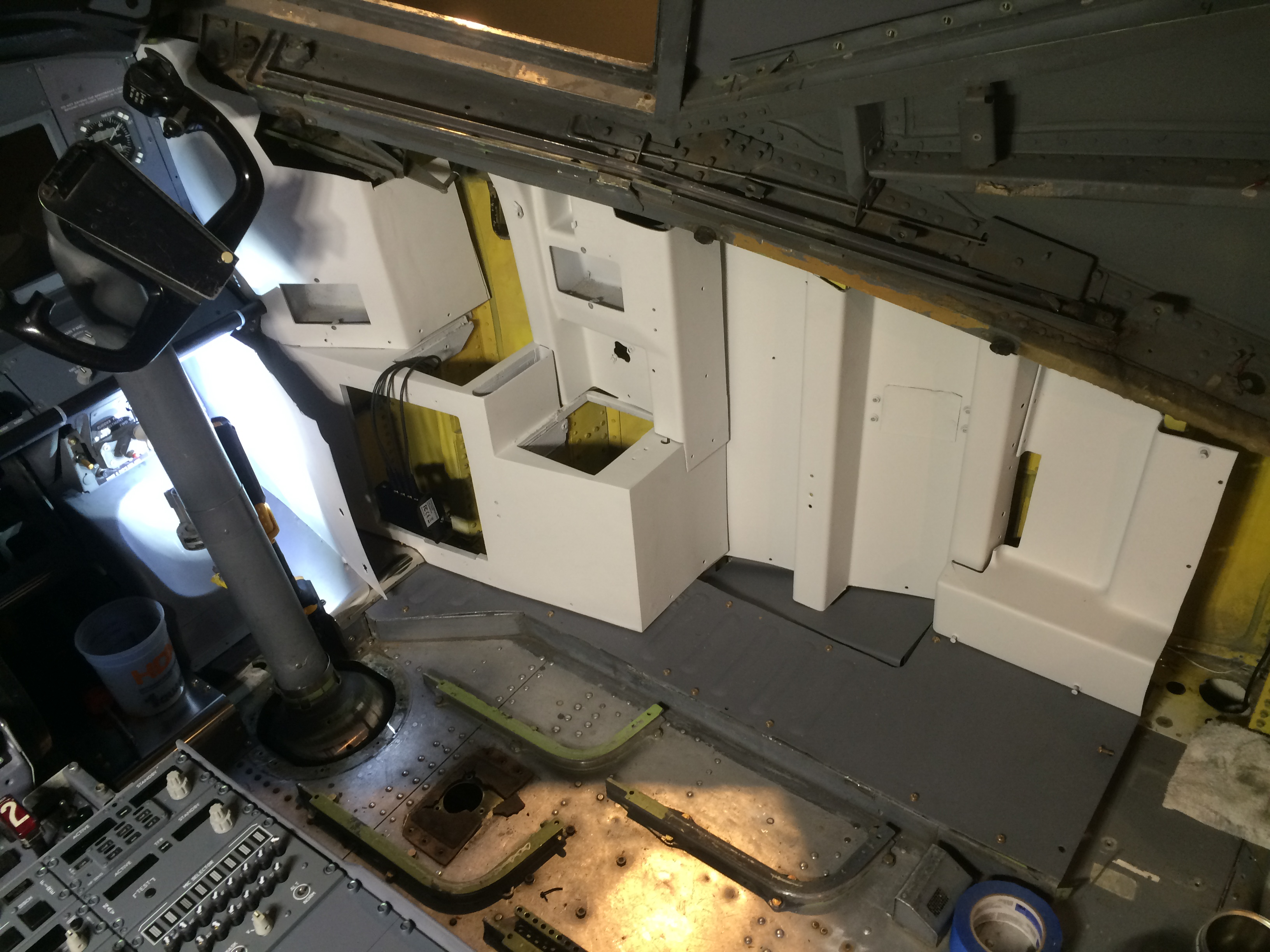
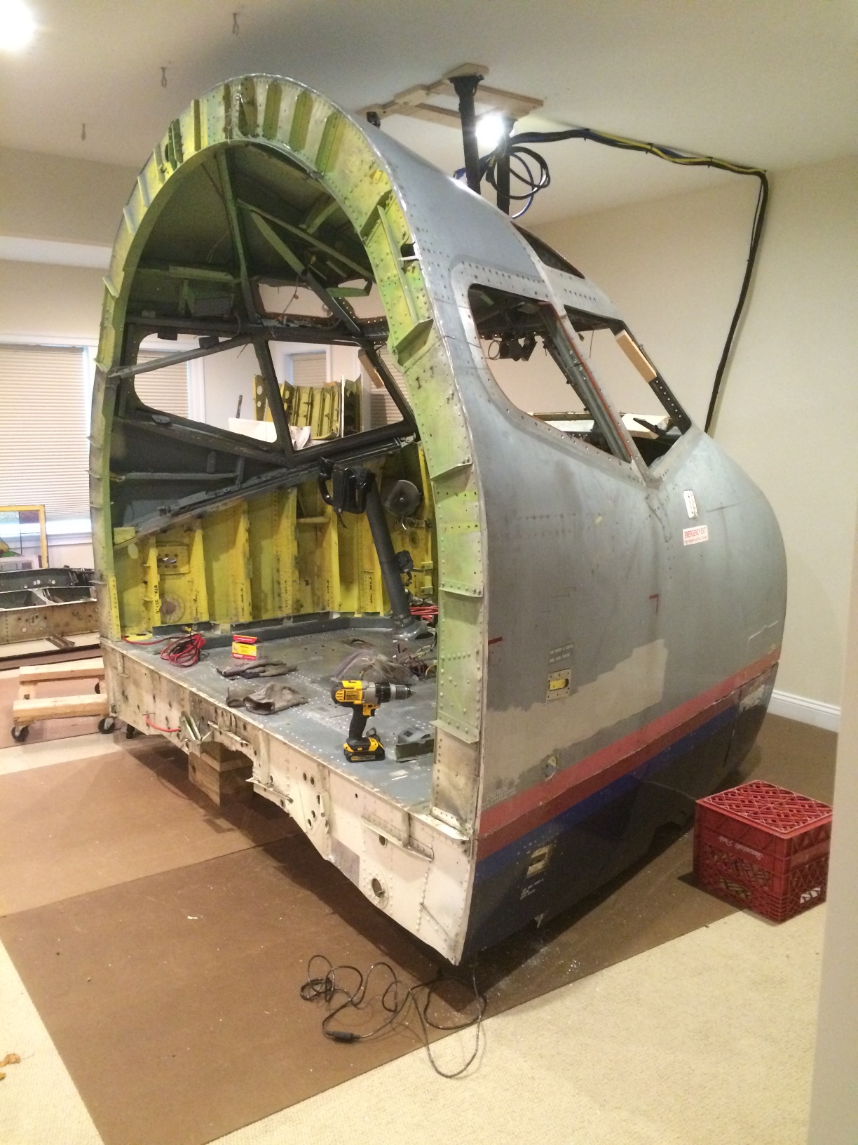
Having finished the bulk of the avionics work, it was time to focus on installing the various trim pieces, mostly plastic, that finish off the cockpit. In order to have the maximum amount of working room, I decided to complete most of this task prior to installing seats and the circuit breaker structures that make up the back wall of the cockpit.
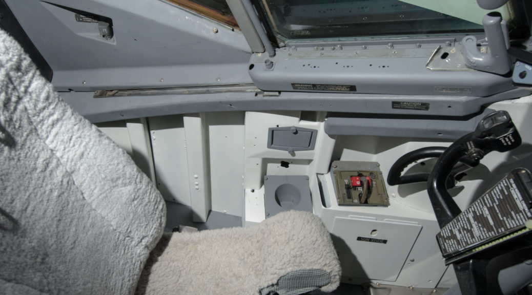
Captain side trim nearing completion. P2 and P3 windows are installed. Oxygen mask box, cupholder and ashtray are all painted gray.
My cockpit sat in the boneyard for about two years before I bought it on eBay in 2011. All of the cockpit windows were certainly removed early on, because they are very expensive parts and the market for serviceable used units is robust. The result of this was that the remaining parts of my cockpit were exposed to the elements for the three year interval after the airplane landed there after a brief flight from Chicago in 2008. The dust and rain that entered the cockpit caused a number of the fasteners holding the trim in place to become seriously stuck. Once again PB penetrating catalyst came to the rescue, but not all of the fasteners were easily removed. Many required turning with locking pliers (eg vice-grips), and the most stubborn ones required drilling out. Just removing the trim took several months back when the airplane was still in the hangar.
The cockpit in 2012, after the circuit breaker walls were removed and the tedious task of trim removal was starting.
As this trim was 25 years old, many of the plastic pieces were very brittle, and some pieces were unavoidably damaged during removal. Several broken pieces needed mending, which I did by backing the pieces with fiberglass, then filling in the cracks with 3M flowable finishing glaze and sanding before painting.
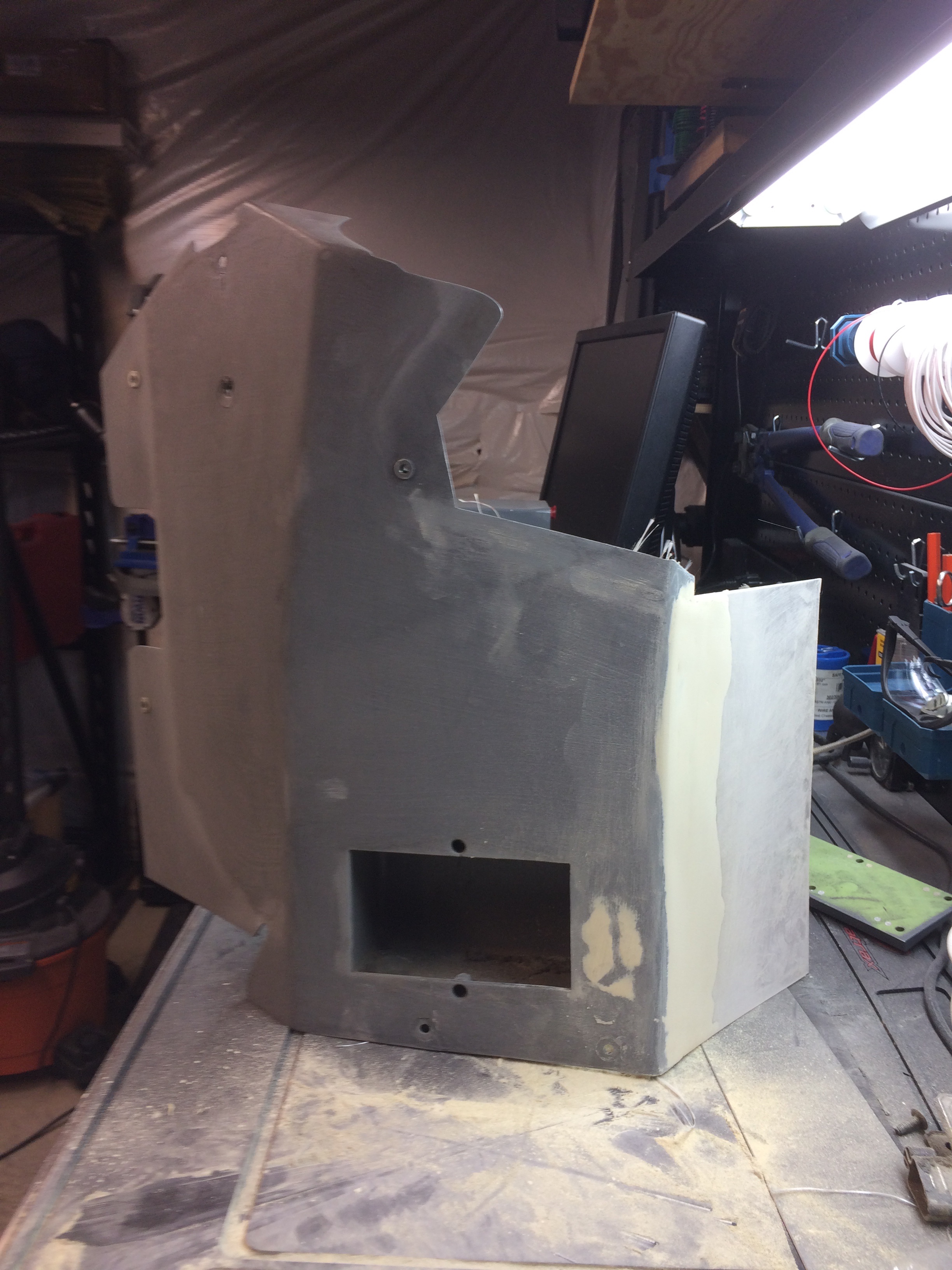
FO side trim piece during restoration. Beige spots are 3M flowable finish glaze after sanding. Open space at the bottom is for factory original ashtray.
The only unpainted metal parts were the rudder skids, which were easily polished with an orbital buffer and some 3M rubbing compound. The corrugated metal floor pieces outboard of the seat J-rails were stripped and painted.
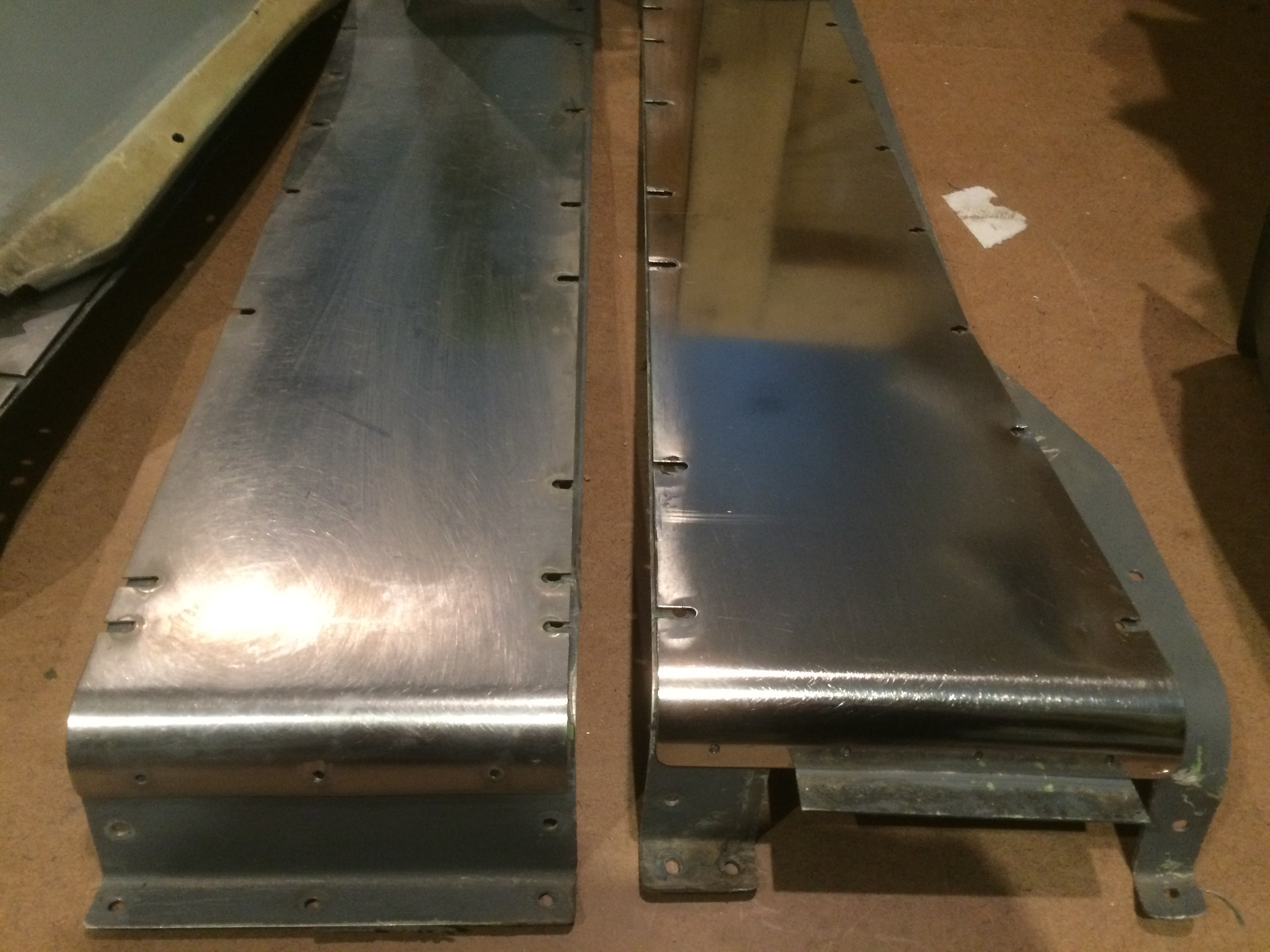
Rudder pedal skids before and after restoration. This is where the pilots rest their heels when their feet are on the rudder pedals. Boeing must have given up painting these because they get so much wear. Easy to get a mirror finish with a little 3M rubbing compound and an electric buffing tool.
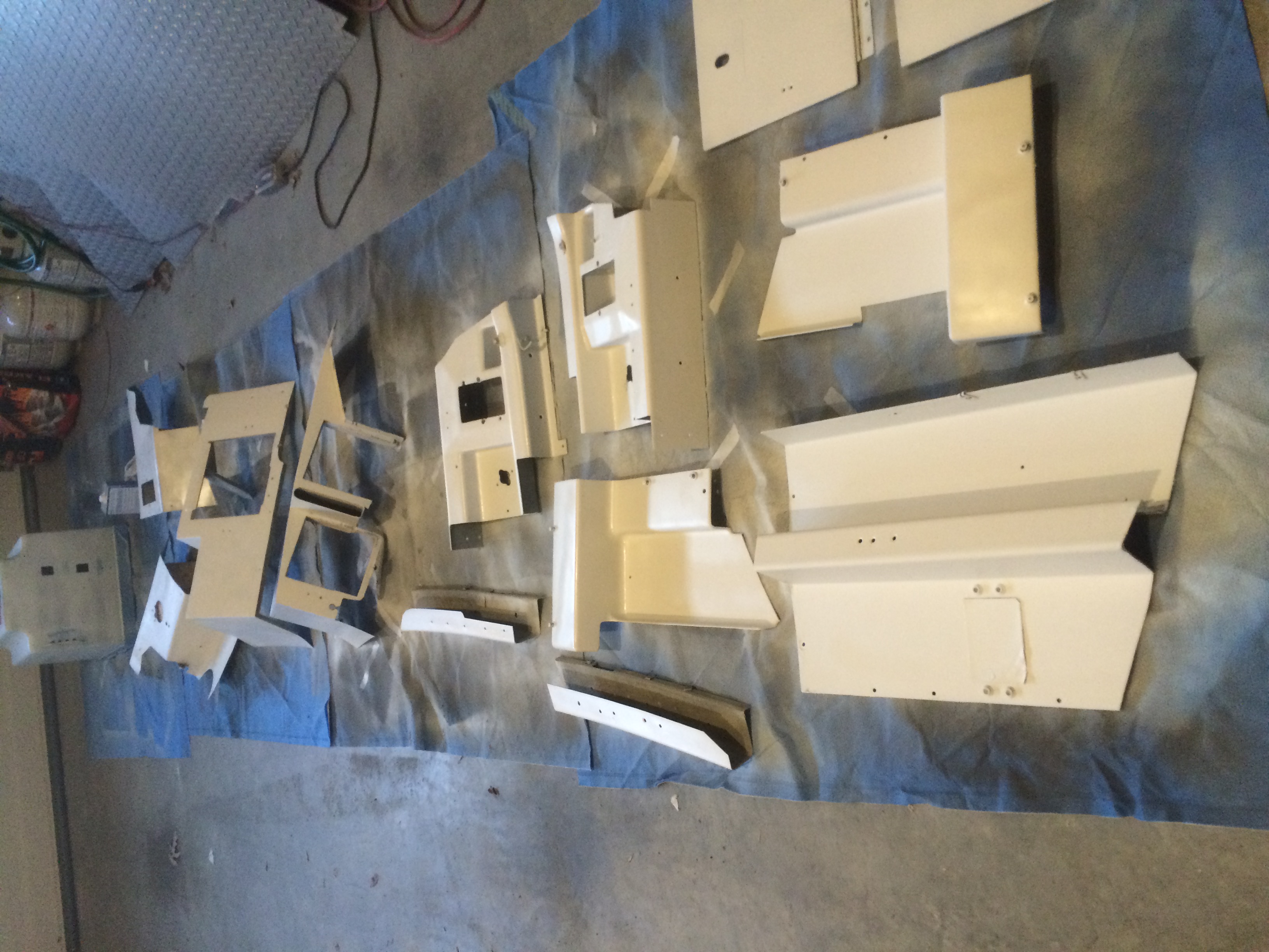
The trim pieces as well as the screw heads were painted according to location. My cockpit is a classic 737 model, but I was building a 737 NG model, so I painted the lower parts of the trim in a light gray primer obtained at Home Depot. The upper pieces were painted in a medium gray primer. After applying two coats, I applied a clear matte finish on top of each of these to eliminate the sandpaper texture of the primer.
Off white paint for the lower sections of trim. The pieces themselves are pure classic 737, but the paint color lends the illusion of an NG model cockpit.
P2 windows and associated trim pieces after painting with medium gray.
The reassembly process was a bit of a jigsaw puzzle, made easier by the mounting points left behind on the OEM shell. The basic installation scheme is to start low and aft and work your way forward and to the top, as many of the pieces overlap in a specific configuration. Straight awls are helpful for lining up holes to the nutplates. After the trim pieces were installed, various accessories were installed on top, including cupholders, oxygen mask storage boxes, and ashtrays. Believe it or not, when this airplane came off the assembly line in 1988 the cockpit was equipped with ashtrays. Of course this is now a non-smoking cockpit. At some point in the future I will replace the ashtrays with custom sheet metal pieces with USB connections to each of the computers running the simulation, but until then the original (very clean) ashtrays remain in their positions.
FO side trim during installation. Light gray piece at upper left needed extensive repair, shown in photo above.
One of the last major avionics projects prior to closing up the cockpit with trim was the installation of the avionics pedestal. This piece is screwed to the floor and has Dzus rails for mounting various avionics including the radio control heads.
Boeing OEM pedestal prior to removal. Note the entire structure was removed prior to tackling this part of the project, given how stuck the fasteners were. Throttle quadrant and flight control removal was delayed until even later, when the floor was in vertical position.
The pedestal itself is a Boeing OEM unit that was installed in the cockpit I originally bought in 2011. Removing the pedestal required a great deal of patience as the screws holding it in place were exposed to the elements for a couple of years while the cockpit was waiting in the boneyard for me to rescue it. PB penetrating catalyst was essential to this task. I stripped the pedestal and refinished it with a self-levelling compound made by 3M. I then painted the unit in the style of an NG model 737, with off white for the body and gray trim around the top. Clear matte spray finish makes for a better appearance and covers up the sandpaper texture of the primer.
Pedestal mount, looking forward. Gray structure at the top is the base of the throttle quadrant. Gray frame in the center of the picture is the pedestal base. As this piece crosses the midline, it was used to index the left and right sides of the floor during reassembly.
The power and USB cables were previously run under the floor back when it was still in vertical position. I chose a combo 12v/5v power supply to provide 12v to the FDS-SYS3 card and 5v for the lighting. This power supply also wound up being used for two USB hubs that wound up inside the pedestal. The backlighting is on a FDS-IBL-DIST-DIM with a FDS-IBL-DIST-EXP card. A 24v power supply was added later when I finished interfacing an OEM fire panel.
Pedestal during installation. Top of frame shows aft part of throttle quadrant and fire panel. FDS-SYS3 interface card mounted on wall on the left, USB hub on the top right. Small interface boards on either side are FDS-IBL-DIST-DIM boards. Avionics modules will be installed on Dzus rails.
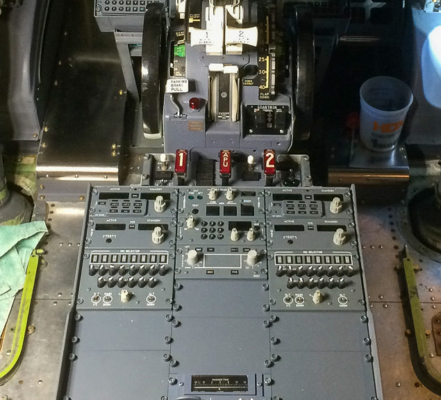
After screwing the pedestal back onto the OEM nutplates, I connected the various pedestal modules one at a time. My pedestal has 2x multicom units, 2x NAV radio heads, 2x dummy audio panels, one transponder control, a cargo fire panel, a dummy radar control panel, aileron/rudder trim panel, a door access panel, and a lighting control panel.
Avionics pedestal complete after installation of modules, all manufactured for the simulation market by Flightdeck Solutions except the fire panel seen at the top.
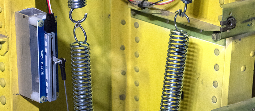
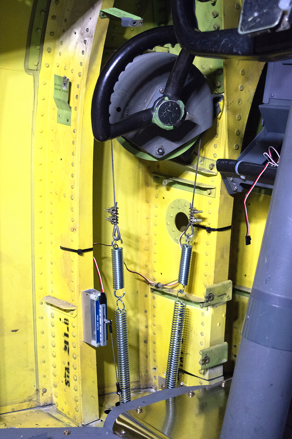
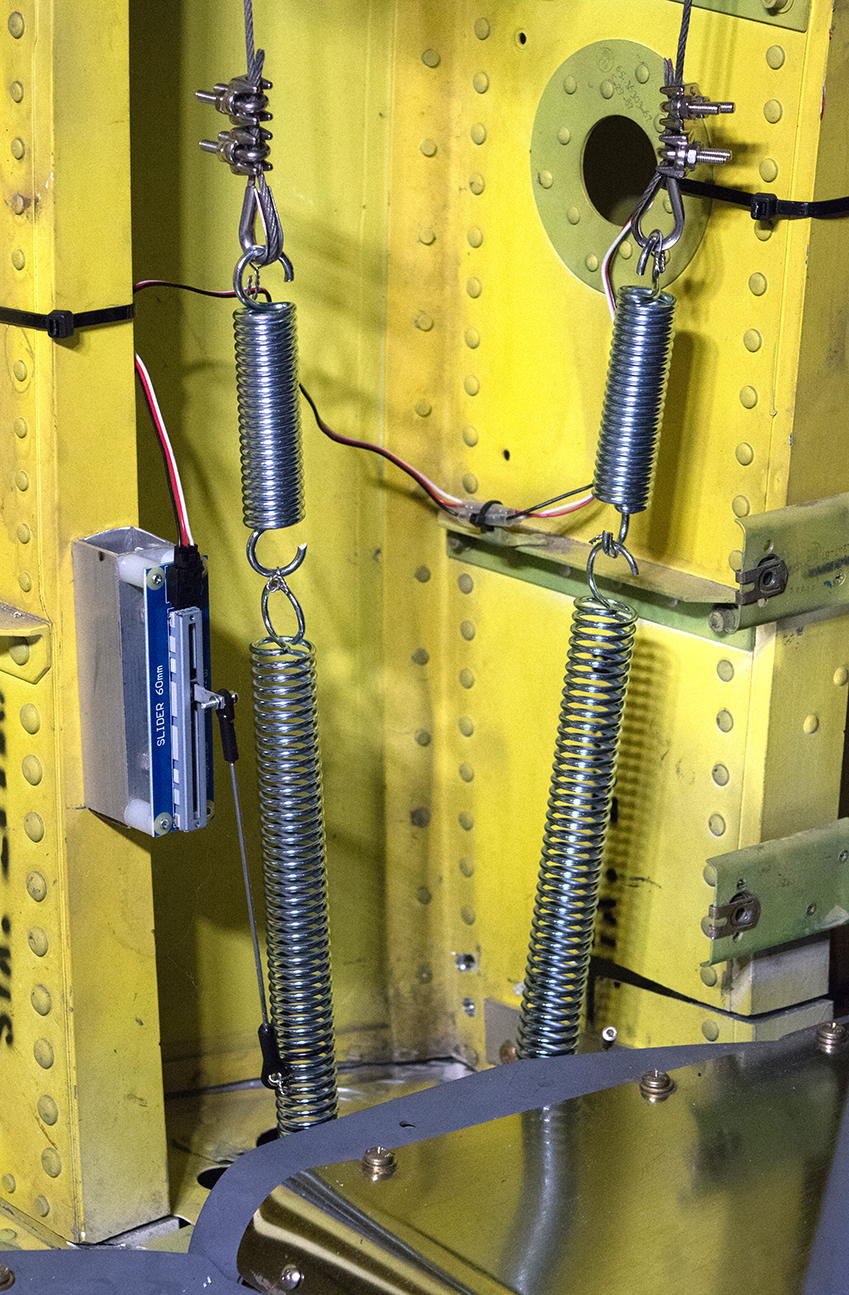
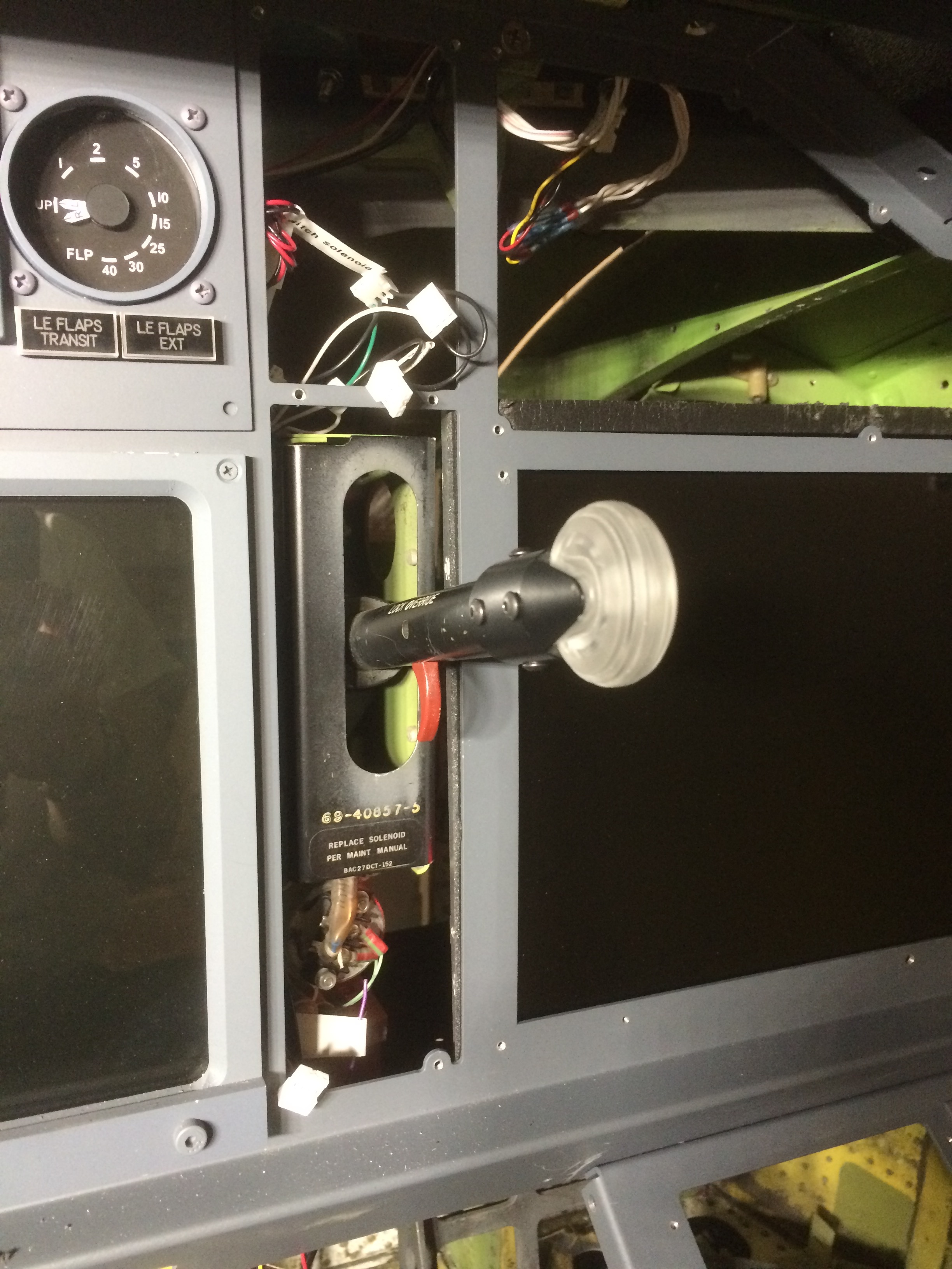
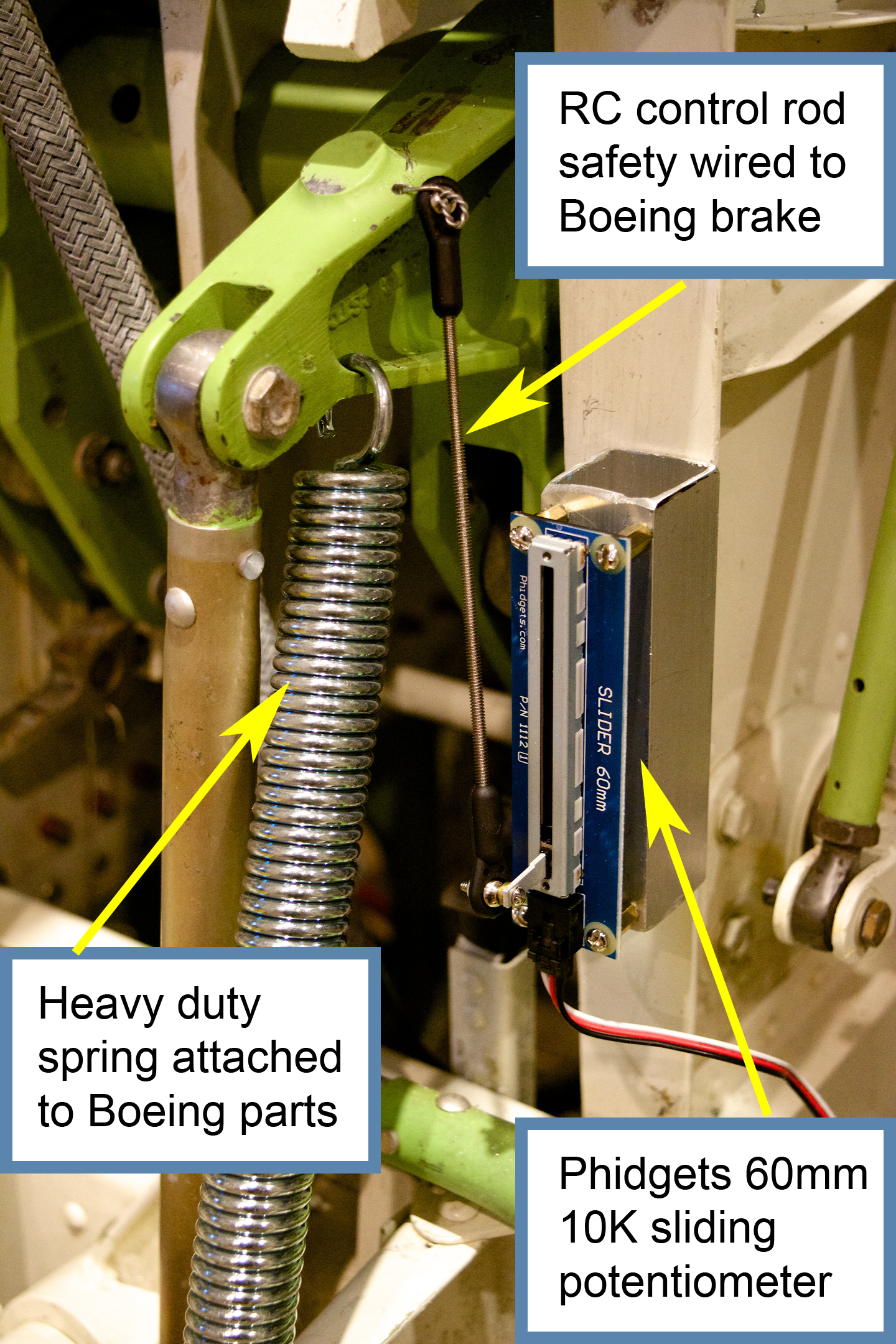
Nose wheel tiller interface. Gray and black components at the top are Boeing OEM. Cables were cut, loop ends installed, and heavy duty springs fitted with bottom ends attached to cockpit floor. Intreface via Phidgets 60mm sliding potentiometer.
Having finished the bulk of the avionics installation, it was time to think about installing the plastic trim pieces in the cockpit. Before proceeding with trim installation, I had a few remaining tasks. In this post I will describe how I interfaced a Boeing OEM nose tiller.
When I purchased my cockpit in 2011, the complete nose wheel tiller mechanism was present. It worked fine, but was in need of cosmetic improvements. I was looking for a way to refinish the wheel itself, which is covered with a very thick, chip resistant coating, when a new-old-stock (NOS) OEM unit came up for sale on eBay…$79.50 plus shipping.
Since the initial design of the Boeing 737, nose wheel steering on the ground has been augmented by a metal control wheel just to left of the Captain’s thigh. On the ground, the airplane can be steered by differential thrust on the engines, but for fine control, especially at low speeds, the steering tiller is used to direct the nose wheel. Larger Boeing aircraft have this control duplicated for the FO, but in the 737, only one tiller is installed on the Captain’s side. In the actual aircraft, the tiller mechanism is connected to the rudder pedal linkage under the flight deck floor via steel cables. In the interest of time I elected to implement my steering tiller as an independent unit.
Detail of nose wheel tiller interface. Phidgets 60mm sliding potentiometer is connected to the lower aft spring using an RC control rod and safety wire.
I simply cut the steel cables and fitted the ends with heavy duty springs. A short piece of RC modeling rod is used to connect one spring to a Phidgets 60mm sliding potentiometer. This pot is then connected to a joystick card (eg Leo Bodnar BU0836X) and the axis is calibrated in FSUIPC. The video below shows how the RC rod is connected to the part of the spring with an amount of travel that is appropriate to the pot.
Dry fit of FDS FMS/CDU/lower EICAS screen bay on top of the OEM Boeing pedestal. Blue tape covers re-purposed cannon plugs used for throttle quadrant power and logic connections. Large gauge red wires are for circuit breaker switches for dynamic force feedback axes.
Bad simulator blogger. Eighteen months without an update. The truth is that I’ve kept very busy working towards establishing full functionality. The sim is now operational and flying regularly. Almost everything works, and over the next few weeks I will be bringing you up to speed on everything I’ve done since my last post.
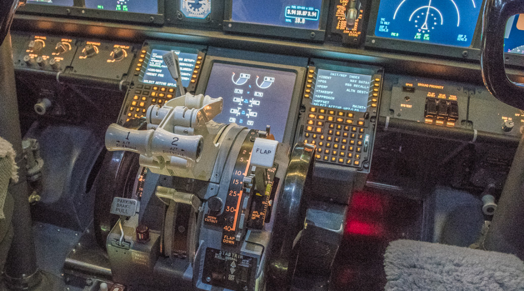
This update today concerns the FMS/CDU (Flight Management System/Control Data Unit) bay just under the main instrument panel (MIP) and forward of the throttle quadrant (TQ). As described in a previous post, the width of this bay is one of the major differences between the cockpit of a classic model 737, which I obtained in 2010, and the the NG model, which I am attempting to simulate.
As I wanted to retain the original equipment manufacturer (OEM = Boeing) rudder pedals, with their linkages and height adjustment mechanisms, I had to figure out a way to taper the FMS/CDU bay so that it remained narrow at the bottom, but was wide enough at the top to fit the two control units, as well as the lower EICAS screen. The difference in width is about 1.75 inches, with the NG model being wider. In the real airplane, the rudder pedals in the NG are more narrow to allow the overall width of the cockpit to remain the same.
My strategy was to retain the OEM frame at the bottom, and use a bay and FMS units built by Flight Deck Solutions (FDS) for the top. The OEM rudder pedals are fairly tall, and the FDS FMS units are fairly deep, having been designed to sit on an angled base when used on a desktop.
Boeing FMC/CDU pedestal after the top was cut off. New aluminum angle was fitted to both sides and notches were cut to allow FDS FMS/CDUs to fit.
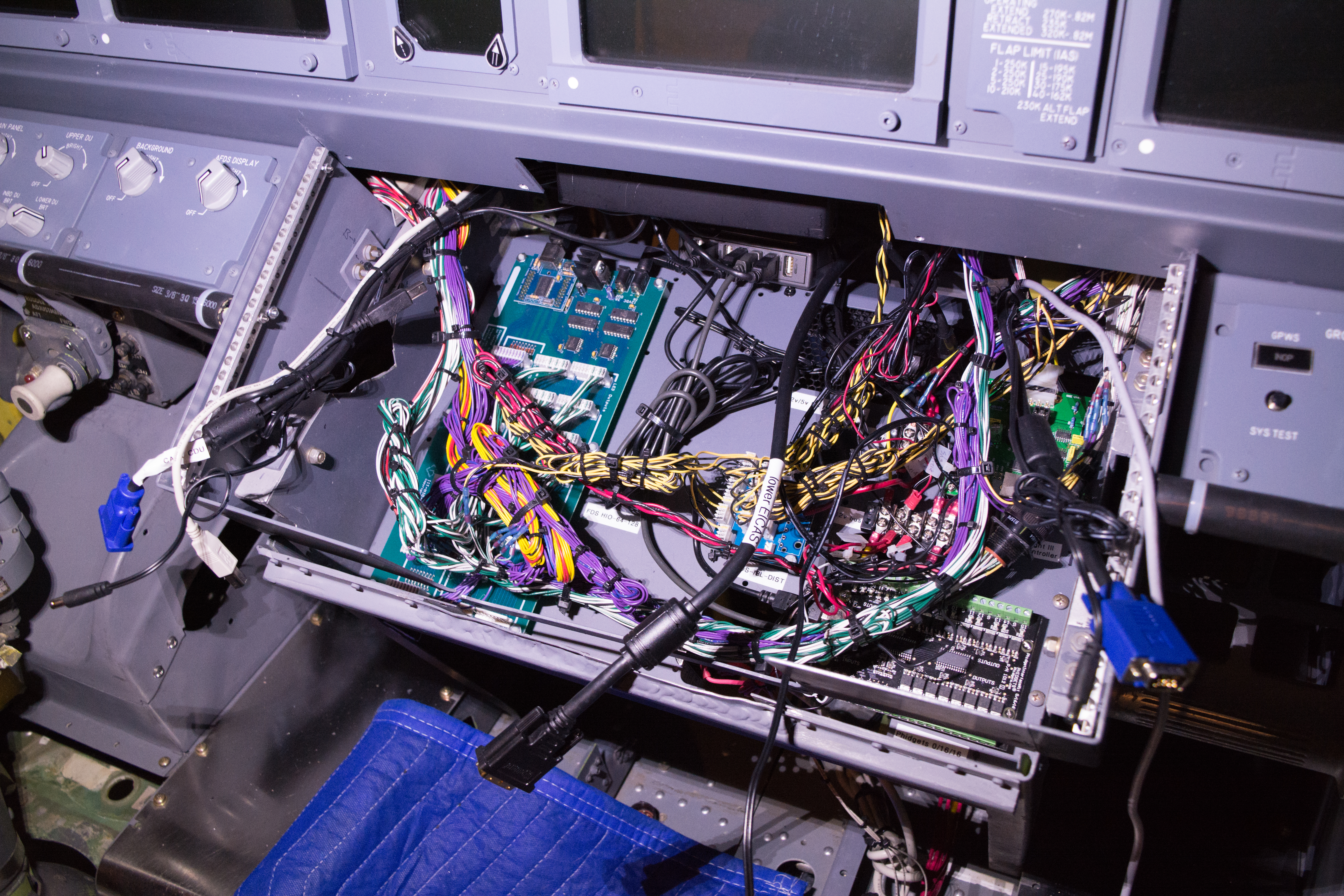
After a number of rounds of measurements, I cut off the top of the OEM base and fitted the sides with 1 inch angle aluminum. I then cut off the top of the FDS bay. I retained the interior shelf from the FDS bay and cut it so it would fit inside the OEM base, allowing a place to mount 4 interface cards, a PC power supply (to provide 5 and 12 volt power) and a USB hub. These components provide interfaces to all of the electronics for the MIP, FMS/CDU units, OEM bell/clacker box, lower EICAS screen and associated panel lighting.
Avionics shelf from FDS FMS/CDU bay fitted into the base of the OEM frame. The shelf is almost completely full with four different interface cards, and a 12v/5v PC power supply and 28 volt power supply mounted below. These devices allow control of switches, annunciators, gauges, backlighting, USB devices and warning noisemakers (fire bell, overspeed clacker). VGA and USB cables provide signals to dual FMS/CDUs and lower EICAS screen.
The cut off top of the FDS bay was similarly fitted with 1 inch angle aluminum. As the MIP was also an FDS product, the forward edge of the FMS/CDU bay had pre-drilled holes that allowed the two components to mate up correctly. Lining up the aft edge of the FMS/CDU bay to the forward edge of the TQ required a number of dry fit adjustments prior to actually drilling holes to set the proper angle for the three screens.
Testing lower EICAS screen and FMS/CDU prior to installation. Setting up display positions is much easier when screens are on a desk.FDS FMS/CDUs and lower EICAS screen mounted in the cut off top of the FDS pedestal.
After assembly, I used the OEM trim pieces to cover the aft edge of my creation. The top of the trim doesn’t quite match up to the aft edge of the FDS bay. Most visitors to the sim never notice because there are so many things to look at and explore. The rudder pedals at the most aft position (for those pilots who are most vertically challenged) clear the bottom of the cut off FDS bay by less than 1/4 inch, but there is no play in these controls as everything is firmly in place.Eventually I will fabricate some custom trim for the outside of this contraption, but for now I am very pleased with the result.
FMS/CDU bay after completion. Aft edge of FMS/CDU on FO shows OEM trim and bell/clacker box mounted below, complete with paint worn from years of FO pant leg brushing up against it.
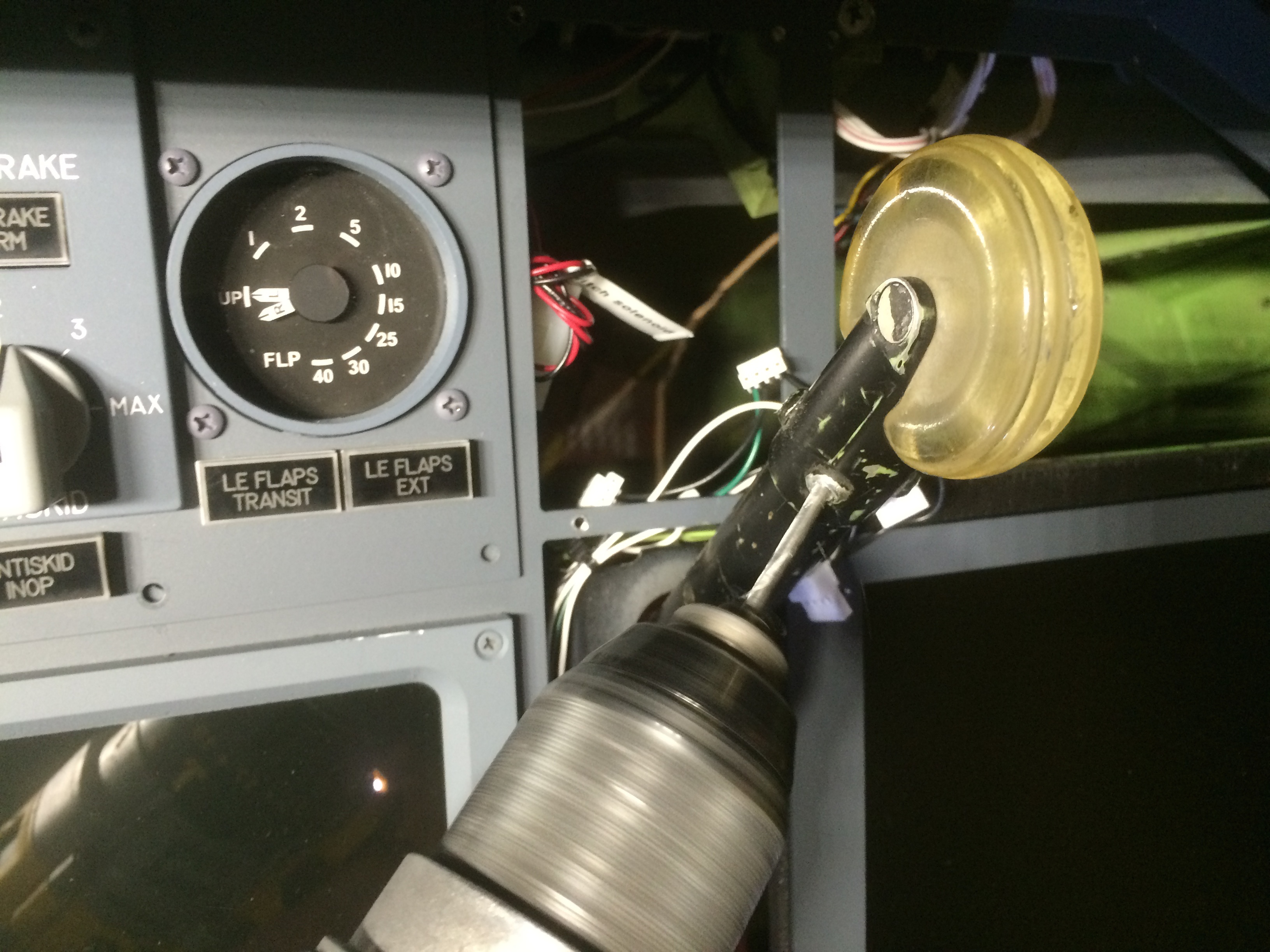
Boeing landing gear lever after installation of FDS NG-style smaller wheel knob.
Having previously installed my original Boeing landing gear lever, I decided to remove the old, yellowed ‘large’ wheel typical of the -200, -300 and -400 models, and exchange it for a smaller one more typical of the NG series.
For the small one, I decided to use the wheel and bracket from an FDS landing gear lever that I had left over from the disassembly of their MIP. This was easily separated after removing four hex screws.
Drilling out rivets from original Boeing landing gear lever with large, classic style wheel knob.
The Boeing bracket holding the wheel was riveted in place, fortunately with solid rivets instead of blind rivets, which are generally much harder to remove. I was able to quickly drill out the rivets and remove the old bracket/wheel combination .
Tapping Boeing landing gear lever to accommodate FDS smaller, NG-style wheel knob holder.
Installing the FDS bracket/wheel required tapping some threaded holes to accept the hex screws. This was a quick modification that looks really good in the end, even if replacing the rivets with screws is not completely authentic.
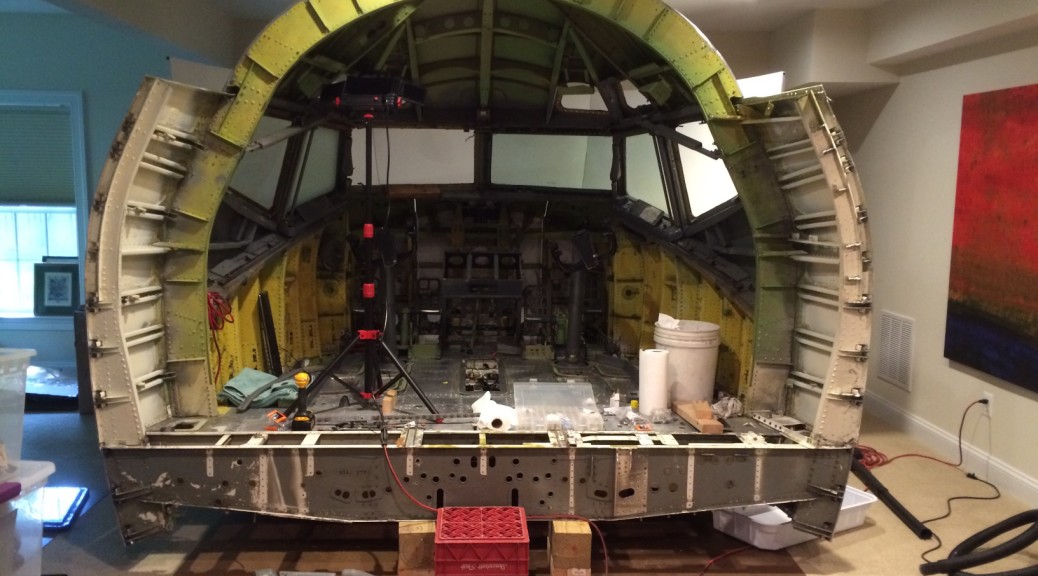
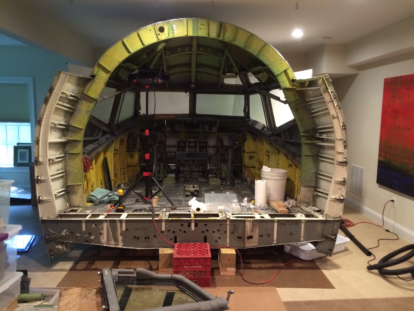
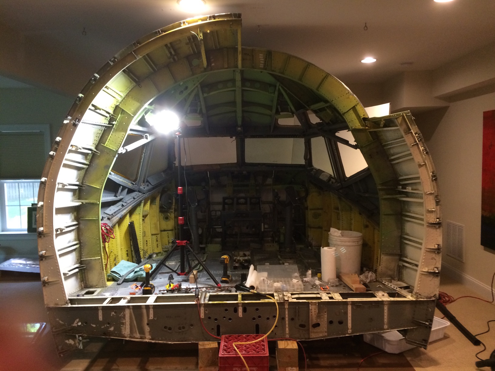
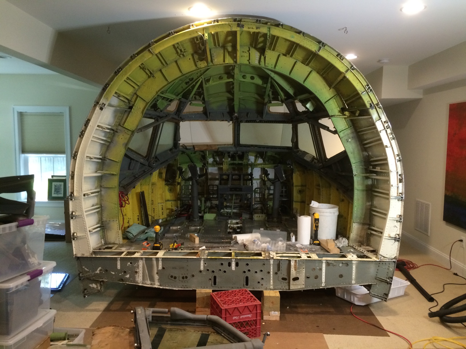
Adding the final aft portion started with the floor. The spar at the bottom of the photo is marked “Station 277.” For now the spar is propped up with pieces of 6×6.
Having finished setting up the forward structure, I decided to scale back my project slightly. As I had the galley and the lav, I had planned to use the full length of the remaining floor to extend out the back. When I saw how much space the forward section occupied, I decided to stop the sim at station 277, which is about 8 inches behind the cockpit door frame. This will leave space for a combination of shelves and remote displays mounted aft of the circuit breaker modules on either side of the door. I plan to leave some of the Boeing structure exposed so that visitors can appreciate the engineering.
Side and top sections of the aft portion of the outer shell ready for assembly.
Station 277 turned out to be about 18 inches aft of the section I had set up, so I spent a few days cutting the aft section pieces down to this uniform length. I reassembled the previously divided floor with screws and nuts, then built up the ceiling in four sections. The reassembled structure came within about 2 inches of my basement ceiling, so it was definitely a good place to stop.
Assembling the aft 18 inches of the outer shell started with the sides.Four out of five sections of the aft 18 inches.
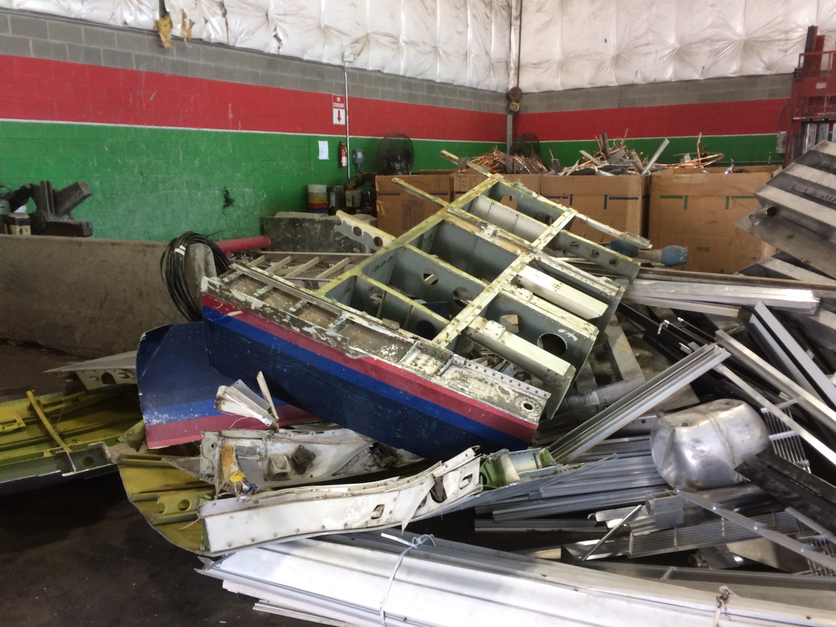
I had a lot of leftover aluminum structure that was aft of station 277, so cut it into small enough pieces to fit in the bed of my pickup, and drove off to the scrap metal dealer, who gave me 40 cents per pound. I’ve decided to sell the galley and lav on eBay. It will be interesting to see if there’s some other person crazy enough to want these things.
No longer needed for the project, the last 4 feet meets the scrap heap some 27 years after it came off the assembly line. Destined to be turned into soda cans, this aircraft aluminum is worth about 40 cents a pound.
The next phase of the reassembly involves shoring up all the structural connections in the cockpit shell. In total there are eleven major sections, and I took advantage of existing rivet holes whenever possible to allow for precise realignment. For the connections between the sides and flight deck, I used steel mending plates of various sizes found with the hinges at Home Depot. The resulting assembly is very solid, with virtually no movement between pieces.
The aft 18 inches, fully assembled and secured. Red milk crate serves as a temporary step onto the flight deck.
The real test of the fit will come when I mount the circuit breaker walls and the cockpit door, but that point will probably not come for several months yet as I have to mount a lot of avionics before I close up the back. Next up: fitting the main instrument panel and mating the bottom of the Boeing FMC bay to the top of the FDS one.
On to the next challenge: modifying the top of the FMC bay to fit two CDUs and the lower EICAS screen.
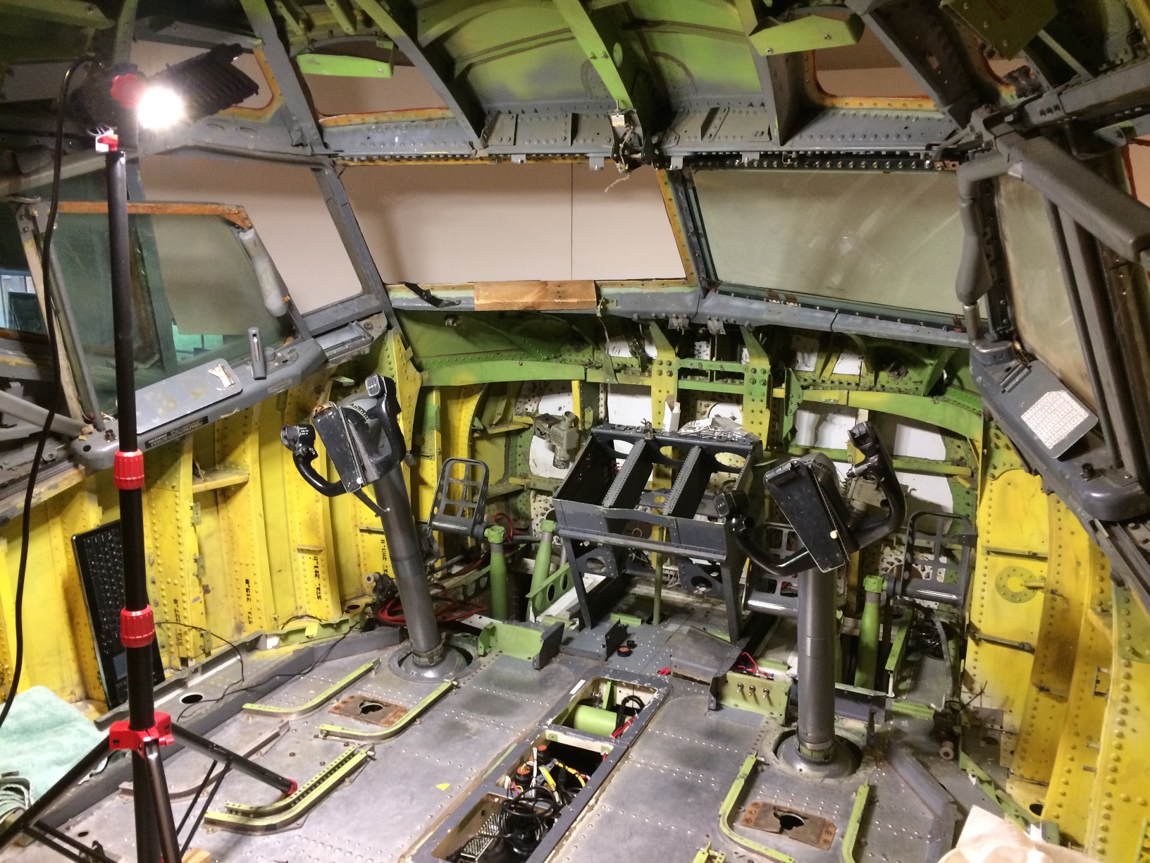
Now that the floor is level, it’s time to start building up the cockpit structure. The second forward level consists of three sections: left, right and center, with the vertical divisions roughly in line with the inboard rudder pedal linkage on each side.
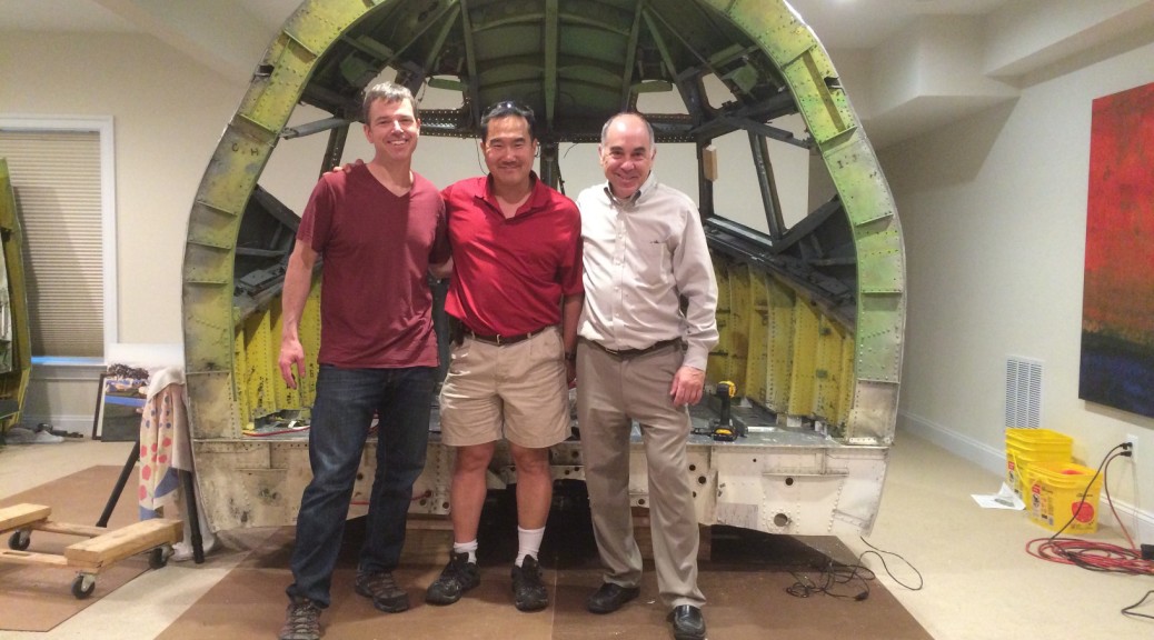
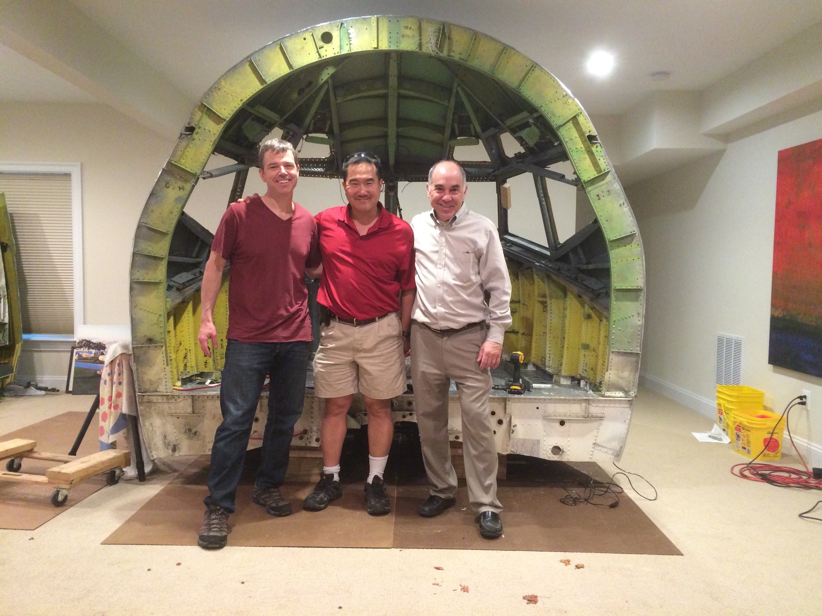
Left to right: Peter Wu, Elmer Choi and Andy Schwartz. Just after hoisting the top onto the sides.
All three pieces are made of aluminum, but there are thick spars that Boeing designed to protect the pilots, and the sections are bulky and heavy. So I enlisted the help of Elmer and Andy, who came over to help me hoist these pieces into place. The sides were easy enough, but lifting the top onto the structure required some planning.
And to think it only took two years from when it was disassembled to get to this point. Once the floor was back on the ground, we were able to move quickly to set up the rest of the structure. Cables on the ceiling are for projectors for the visual system. Amplified USB cable intended for the overhead is seen in the lower center part of the photo. Red and black cable at the aft end of the captain’s side is for overhead AC power.
For some reason I must have been in a hurry on the day that I cut these some three years ago, because I completely neglected to make any indexing brackets. Not really a problem because the windows are structural, and I have an almost complete set of Boeing windows. By mounting these windows and using an awl to line up the bolt holes, I aligned not only the left/right/center sections but also the top to the sides.
At this point in the build I am rediscovering many items that have been in storage for a few years. I had an unwelcome surprise when I pulled out my windows to find what had been advertised as a full set actually consisted of two FO side P1 windows, a matched set of P2 slider windows, and only one of the P3 windows that I needed. Luckily there was a captain side P1 window for sale on eBay at a reasonable price, but the only source of an FO side P3 window is for new old stock at a somewhat less reasonable price. Through one of these window deals I wound up with an extra pair of P2 slider windows, so hopefully these will fetch a good price online and allow me to purchase what I need. For now, I plan to use the captain side P3 as a template to make a plywood insert for the P3 window opening on the FO side. Even the full-motion level-D sims black out these rear windows, so I don’t feel like I’m detracting from the experience by doing this.
Existing Boeing brake mechanism fitted with slide potentiometer to measure brake excursion.
Having overcome the major hurdle of implementing dynamic force feedback, I have been busy performing other tasks that will be most easily accomplished while the floor remains in vertical position. These include wiring the brakes and stick shakers, as well as rewiring the throttle quadrant with salvaged AMP cannon plugs that allows the interface cards to easily detach from the mechanical parts of the unit. I used a 55 pin plug for the switches and pots, and a separate plug with larger 16 gauge pins for the power connections.
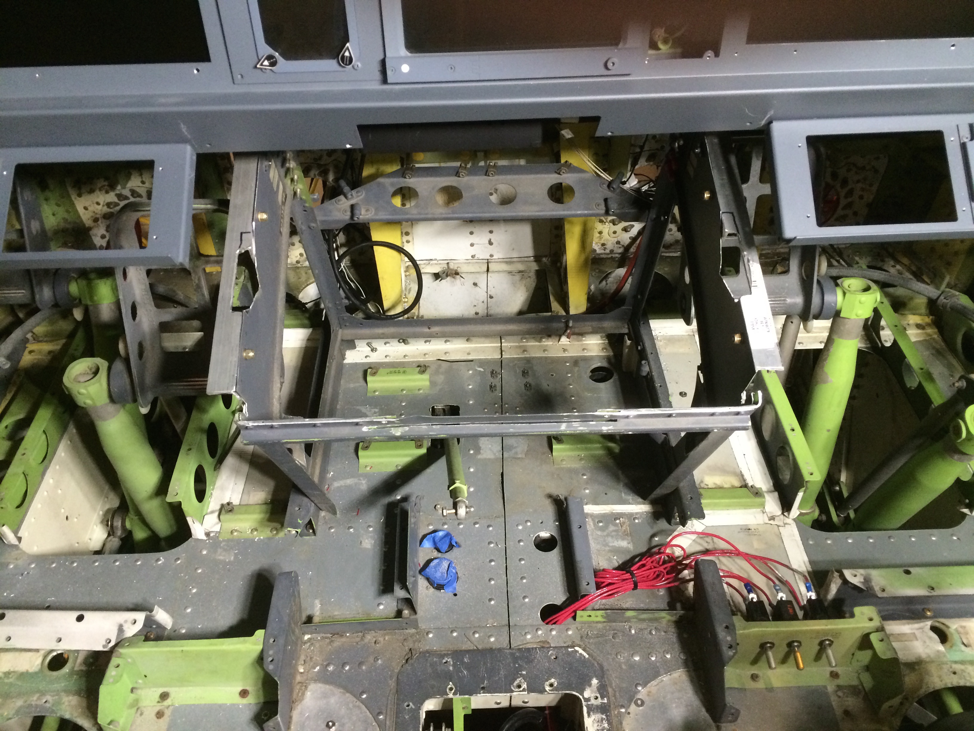
The floor section just prior to flipping back to horizontal. Various cable bundles are visible for connection to components above the floor. Kill switches for dynamic control loading motors are seen just inboard and forward of the FO control column.
I spent at least a week going over the underside, testing all the functions and tidying up cable runs. Once this section is put down into its final horizontal position, there will be only 20 inches between the flight deck and the floor of the basement, so I will still be able to get in and work on things, but it will be a lot less convenient and probably a lot more likely to induce neck and shoulder pain. Twenty inches seems like a lot, but that’s the distance from the flight deck to the floor, and there are a lot of mechanical parts in between, such that there won’t even be room for a creeper.
The floor, finally back in normal horizontal position after years of configuration. Various cable bundles come up from below the floor, to be used as components are added above. All cables below the floor run forward, where computers and power will eventually be located.
The day finally came, and after one final cleaning, I cut the heavy cable ties holding the floor section to the ceiling joists above, and started sliding the section as far forward as it would go in the room. I called my buddy Adrian, a senior F/O at jetBlue, to come over and help me lower it. I figured it would be pretty easy for two of us to lower it down, as it seemed to me that most of the weight was concentrated in the yoke and rudder mechanisms located fairly far forward. It wasn’t that hard, but the aft end was quite a bit heavier than I thought. Luckily Adrian’s fiancee Kelly, herself a Captain and check airman at Frontier, was there to help place the aft floor supports, which I had made from short sections of 6×6 and 2×6. Once we got it down, a quick check revealed that the flight deck was perfectly level in all directions. Looks like my cuts and indexing were precise enough!
The cuts must have been precise enough: a perfectly level floor with no shimming required.
I know, I know…it’s been over a year since my last update. I have been working on implementing dynamic force feedback, a slow but steady process that required designing, and sometimes redesigning, custom made transmissions for driving all three control axes.
I am happy to report that I now have all three axes working after a great deal of calculation, consultation, and trial-and-error experimentation with various transmission designs intended to mate the BFF do-it-yourself force feedback interface cards to the original Boeing flight control structures. There were several examples of such implementations out there on the web, most of which involved expensive custom gearing and none with an original 737 mechanism.
The designer of the BFF cards is extremely helpful with the installation and operation of the cards themselves, but leaves it to the simulator builder to come up with the proper mechanisms for driving the controls. My first step was to consult my pilot buddy Andy Schwartz (of the mechanical engineering firm SSA Engineering) for some badly needed help with the engineering. Armed with some actual Boeing flight control tension specifications from David Allen, Andy confirmed that the specified motors, gears and belts that I had dreamed up would supply the required forces at the man-machine interface.
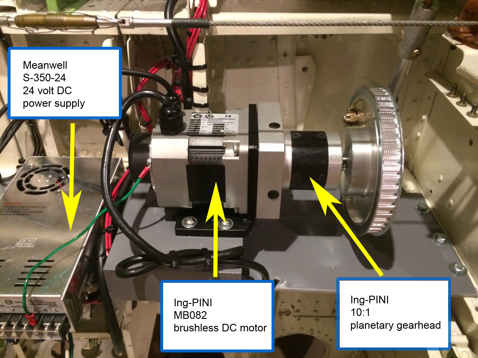
The BFF card designer specified a particular motor from an Italian manufacturer, which does not accept credit cards, Paypal or Bitcoin and required an international wire transfer for payment. The motors themselves arrived almost a month later, and only then was I able to start designing custom motor mounts to fit onto the existing Boeing structure. One of these was fairly simple but the other two were complex shapes that required some time to fabricate using my old friend, the electric 4.5 inch angle grinder. After cutting the shapes from 3/16 inch steel plate, I cleaned up the sharp edges with a polishing disc attached to the same tool. As the steel was not stainless, I applied several coats of gray primer to prevent corrosion before installing into the floor structure. The motors themselves were mounted through a hole drilled in each plate. A rubber/cork gasket cut from a sheet obtained at my local auto parts store was used to help reduce noise and vibration from the motors. A large number of fasteners was used for each mounting plate with the same goal in mind. The largest plates, the one used for the pitch and roll axes, serve double duty as structural supports since they cross the midline and connect and maintain the proper spatial relationship between the two halves of the divided flight deck floor.
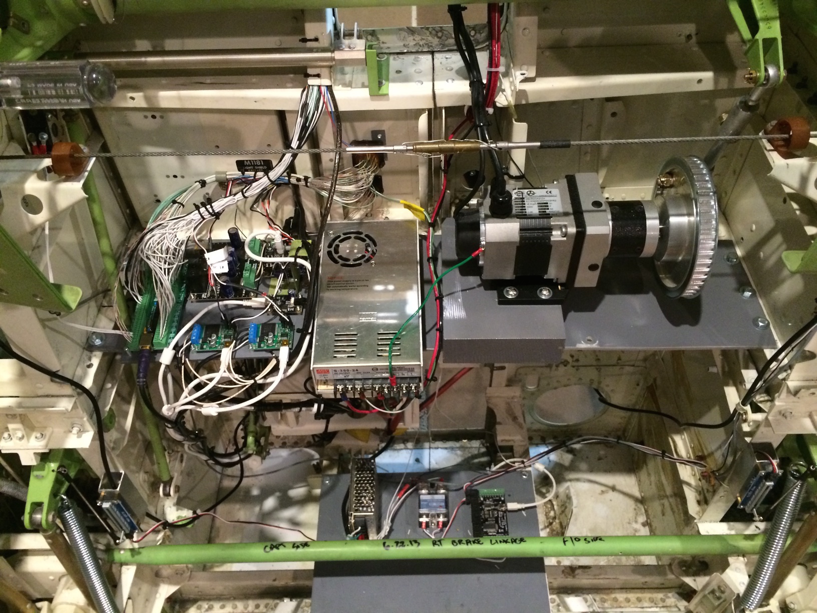
Custom fabricated plates (painted Boeing grey) for dynamic force feedback and interface cards. Top plate, left: a total of seven interface cards, mostly for controlling the throttle quadrant and control yoke buttons. Top plate, middle: Meanwell S-350-24 24 volt DC power supply. Wires in recycled AMP cannon plugs above connect to the throttle quadrant. Top plate: right: elevator motor, planetary gearhead, and pulley/pushrod connected to original Boeing elevator torque tube at top right. Bottom plate, left to right: Meanwell 24v power supply, solid state relay for activating 28 volt devices with 12 volts signals, Phidgets 8/8/8 interface card to measure brake excursion (by sliding potentiometers) and stick shaker activation.
Having finished mounting the motors, I was able to start the task of wiring the cards. Ian provides extensive instructions with the cards, and suggested an inline circuit breaker for each axis to use as a ‘kill’ switch in the event of undesired behavior. I happened to have about ten 28-volt circuit breaker switches lying around as a result of the circuit breaker switch airworthiness directive that became effective for piston Beechcraft aircraft in 2010. The FAA forced operators of these aircraft to replace thousands of these switches with newer models after a few reports of failures and resultant smoke in the cockpit episodes. So I chose three of these with appropriate amperage ratings and installed them in an existing structural support under the FO side left rudder skid. I left enough slack in the wiring to allow them to be repositioned to the underside of the main instrument panel after that component is installed later. These switches are not airworthy per the AD, but perfectly functional for this purpose.
Beech circuit breaker switches re-purposed as kill switches for dynamic control loading motors. For now they are mounted below the FO side left footrest. I left enough slack to allow them to be repositioned below the FO side of the main instrument panel later.
I would have preferred to have mounted all three BFF interface boards somewhere above the flight deck to facilitate their maintenance, but practical concerns prevented me from doing so. Because the motors have integrated position sensors, the signals carried by the small gauge wires back to the interface boards are very low voltage and Ian recommends not extending the shielded wire bundles coming from the motors. The cable bundles are short, no more than three feet. As there are also large heat fins on the cards, they could not be located in an enclosed part of the cockpit without complex cooling systems including ducting. So I had no choice but to mount the cards underneath the floor in areas that would be relatively accessible with a mechanic’s creeper.
Custom fabricated plates (painted Boeing grey). Top: initial yaw axis motor mount, left in place to add structural stability. Middle: three BFF BLDRV-12/24 cards for dynamic force feedback. The plate also has two fans for heat sink cooling. The middle of plate has the roll axis motor, with two pulleys for setting the correct tension on the timing belt. Bottom: original Boeing elevator torque tube, painted in zinc chromate green.
The BFF cards can be daisy chained together in order to allow the use of a single USB interface cable. This is advantageous because the boards were designed to use a specialized USB PICAXE cable that uses a 1/8 inch mini stereo jack that costs $30 and must be ordered from the UK. The software identifies the different control axes by the use of jumper pins that are set on each board. Ian recommends that all three interface cards be co-located, so that each length of daisy-chain serial cable between boards are no more than eight inches to eliminate noise. I could have achieved this by mounting one card above the roll axis motor mount plate, but this would have made it very difficult to access from the underside, so I elected to purchase a second PICAXE cable to allow me to locate one interface card about 12 inches away from the other two. As also recommended by Ian, I installed two cooling fans, one for the pitch axis and one that is shared by the roll and yaw axes.
It took a few weekends to cut, crimp and run all the wire between the wall outlet, power supplies, and interface boards. I took advantage of some existing Boeing light fixtures used by mechanics when accessing the forward flight control bay, using another old Beech circuit breaker switch in the process. I will be happy to have these lights operational the first time I have to venture under the flight deck on the creeper.
When I first applied power and fired up the BFF test software, all three axes moved, but not very much. After a few emails exchanges with Ian, I got the pitch and roll axes moving but it was clear the yaw axis, with the belt-driven design that I came up with initially, was never going to work because the motor needed to make at least 120 degrees of revolution in order to achieve initial calibration. So I elected to relocate the yaw axis motor from the midline to a place just outboard and forward of the rudder crossover linkage. I was hoping to build a transmission with spare parts on hand, but a brief experiment with direct drive with a pushrod and the largest gear I had in stock resulted in the same problem: not enough rotation to pass the calibration routine. So I ordered two additional timing belt pulleys, fitting the small one to the motor and the large one to a custom fabricated shaft/plate assembly that attached to the Boeing mechanism. This replaced an original autopilot component made out of plastic, which was apparently designed to shear in the event of a control jam.
Yaw axis drive mechanism. The small silver timing belt pulley on the right is mounted to the motor shaft, while the large silver pulley to the left is mounted to the Boeing mechanism. The black pulley in the middle sets the proper tension.
The roll axis is controlled by a motor mounted in the midline, fitted with a timing belt pulley and long belt with a number of flat pulleys to correctly set the tension. I was able to find some blocks online that were cut with the timing belt pitch, through which the ends of the belt were sandwiched. I then drilled a hole through the end of each block, passing an existing Boeing cable already connected to the aileron/spoiler controls.
This axis initially had too much slack to calibrate the motor. A call to David Allen revealed that there is a spring inside the FO side aileron hub that allows the Captain and FO side aileron/spoiler controls to decouple in the event of a control jam. Conveniently, there was a rigging pin hole in the mechanism used to immobilize the spring. After testing out what David promised me was true, I simply tapped some threads with a 3/8-16 tap, cut a countersink, and inserted a screw, locking the aileron and spoiler hubs together, resulting in a much smoother mechanism.
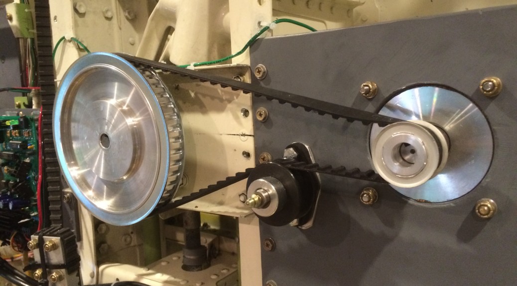
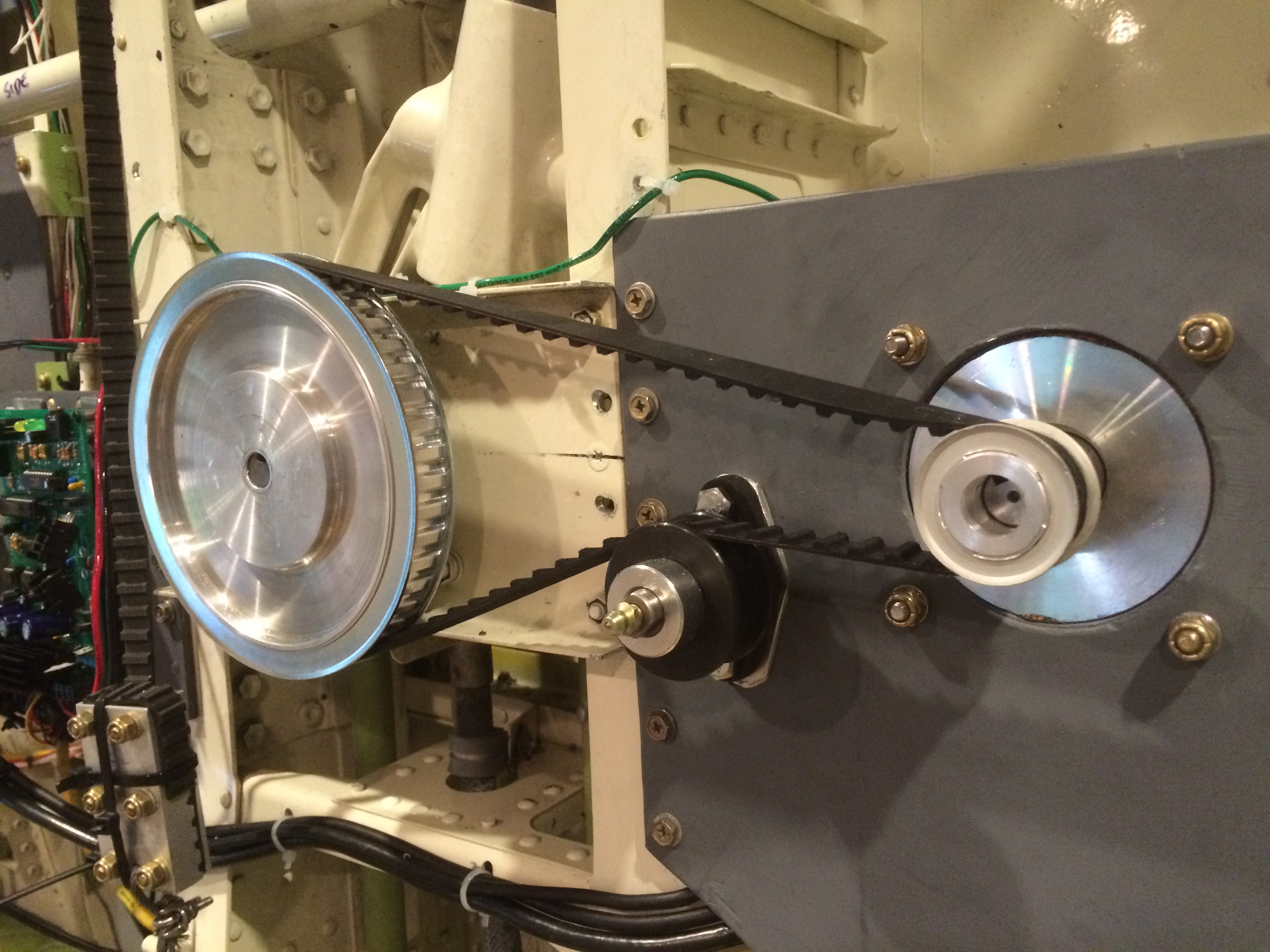
The pitch axis motor is mounted to a custom fabricated plate that crosses the midline to help index the two halves of the flightdeck floor. A thick aluminum block moves the motor close enough to the elevator torque tube to use the existing Boeing mechanism. The pushrod seen connected to the large silver pulley to the right is connected to a tab on the Boeing elevator torque tube.
The pitch axis motor is fitted with a NEMA 34 planetary gearhead with a 10:1 reduction ratio, a simple, cost effective alternative to building a custom transmission. The planetary gearhead was then fitted with a large pulley which was then attached via a pushrod to a pair of existing tabs on the elevator torque tube.
After reinstalling the control columns and re-linking the rudder pedals and brakes, I started mounting springs and heavy duty drawer slides to implement static control loading like that provided by the excellent gear made by Northern Flight Sim. While searching online for parts I came across Ian Hopper’s force feedback site, where he sells hardware and software for implementing force feedback for mid size (think a heavy duty control yoke, like a CH Products yoke made out of metal parts) and larger cockpit setups.
After discovering this I became obsessed with adding this functionality to my simulator. My basement is fairly big, with nine foot ceilings, but I know I will never have enough room for full motion. Adding force feedback would lend a great deal of realism to my setup. Force feedback adds two characteristics simultaneously: dynamic control loading, so that the pilot feels the aerodynamic effects of turbulence and configuration changes, and autopilot functionality, so that flight controls move appropriately when the autopilot is engaged.
This may turn out to be the most challenging hurdle in the project. Ian has created an excellent, highly cost-effective solution to this problem, but he leaves it up to the buyer of his products to properly construct the mechanisms that connect to this controller cards and specified motors.
I have an advantage in that my flight controls were built by Boeing to withstand years of abuse, so all I really have to do is design three transmissions each using this small motor to create realistic forces on a larger scale. It is this particular problem that has had me stumped for the past three months, trying to specify the proper transmission in the most cost effective way. I know it can definitely be done, the question is how?