I just posted a new video presentation about my flight simulator. It’s about 45 minutes long and shared for those of you interested learning more about the project in greater detail.
I’ve given this presentation each of the past two years at EAA Airventure in Oshkosh, WI. I hope you all enjoy it and I welcome your comments and questions.
If you are attending Airventure 2017 in Oshkosh, WI, be sure to make plans to attend my live presentation on my simulator project in Forum 6 on Thursday, July 27 at 2:30pm. For the true airplane enthusiast, there is no better airshow to attend. I look forward to meeting many of you there!
Just after completion of installation of Boeing OEM TQ and pedestal. TQ was heavily modified by Art May-Alyea at Northern Flight Sim, with custom interfacing to provide functionality. Pedestal components by FDS, except the fire panel, which is Boeing OEM.
Having finished the modification of the FMS/CDU bay, I continued my top-to-bottom avionics installation. One of the most critical components, the Boeing throttle quadrant, is located just aft of the FMS/CDU bay.
The TQ I have was purchased several years ago from Art May-Alyea at Northern Flight Sim. Art has a wealth of experience converting old TQs from classic models to closely resemble those used in the NG. He completely disassembles the units, refinishes and paints all the components, installs microswitches to detect every switch position including every detent on the flap lever, then fits the assembly with motors for the trim wheels and throttle levers, as well as servos for the speed brake lever and trim indicator.
Art supplies the TQ conversion with bare wires coming out the front, and interfacing is up to the user. Full details of how I chose to complete the interface will be described in a later post, but the short version of the story is that most of the TQ is connected to a BU0836X joystick controller card from Leo Bodnar. The 12v motor driving the trim wheels are connected to a PhidgetsMotorControl HC card. The throttle levers are driven by two 12v motors fitted with slip clutches and interfaced to two Pololu Jrk 12v12 cards.
The pedestal itself is a Boeing OEM unit that came with the full cockpit I purchased from eBay in 2010. The frame was removed, fully stripped, restored and repainted in the colors of a typical NG model prior to reinstallation. All of the radios and other avionics in the pedestal were provided by FDS, and are purpose built for the simulation market. The one exception is the fire panel in the most forward part of the pedestal frame: this is a Boeing OEM unit that I reverse engineered and will describe in a future post.
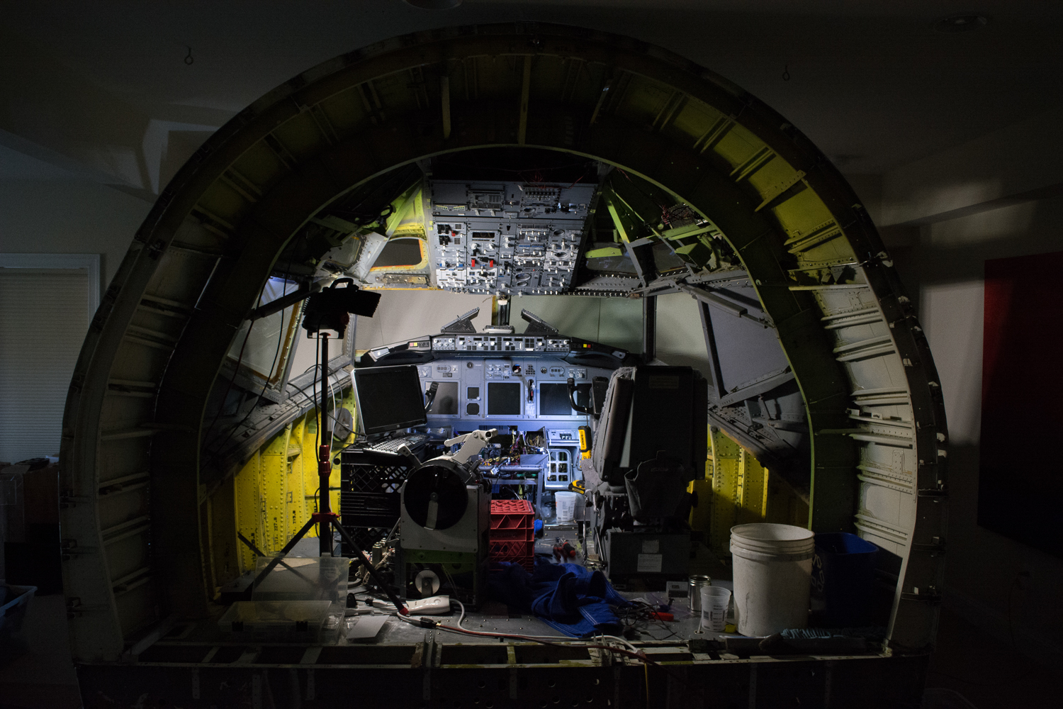
Avionics installation in progress. Overhead, MIP and FMS/CDU bay essentially complete. Preparing to install TQ. FO seat installed temporarily to have a place to sit while performing avionics testing. Milk crates used as computer monitor and keyboard stands.
Prior to proceeding with installation of the trim pieces and back wall, I spent several months checking avionics functionality to determine whether I would need to run any additional wires behind any of the panels. Access to the back of the overhead panels is fairly easy thanks to FDS mimicking the OEM design . I didn’t think of everything, but I got most of the major kinks worked out prior to proceeding with the finish work.
FDS forward overhead panel viewed from the forward position. Boeing OEM mount allows the panel to swing down for maintenance access by turning two Camloc fasteners. FDS-SYS1X interface card at the top has capacity for 128 switch inputs and 256 LED outputs. Gauges are by Flight Illusion. Solenoid starter switches at the bottom are Boeing/Cole OEM units interfaced via FDS-SYS-R1X card. Purple wires run to switches and annunciators. Grey ribbon cable to gauges. Yellow and black wires control 5v panel backlighting.
If you are attending Airventure 2017 in Oshkosh, WI, be sure to make plans to attend my live presentation on my simulator project in Forum 6 on Thursday, July 27 at 2:30pm. For the true airplane enthusiast, there is no better airshow to attend. I look forward to meeting many of you there!
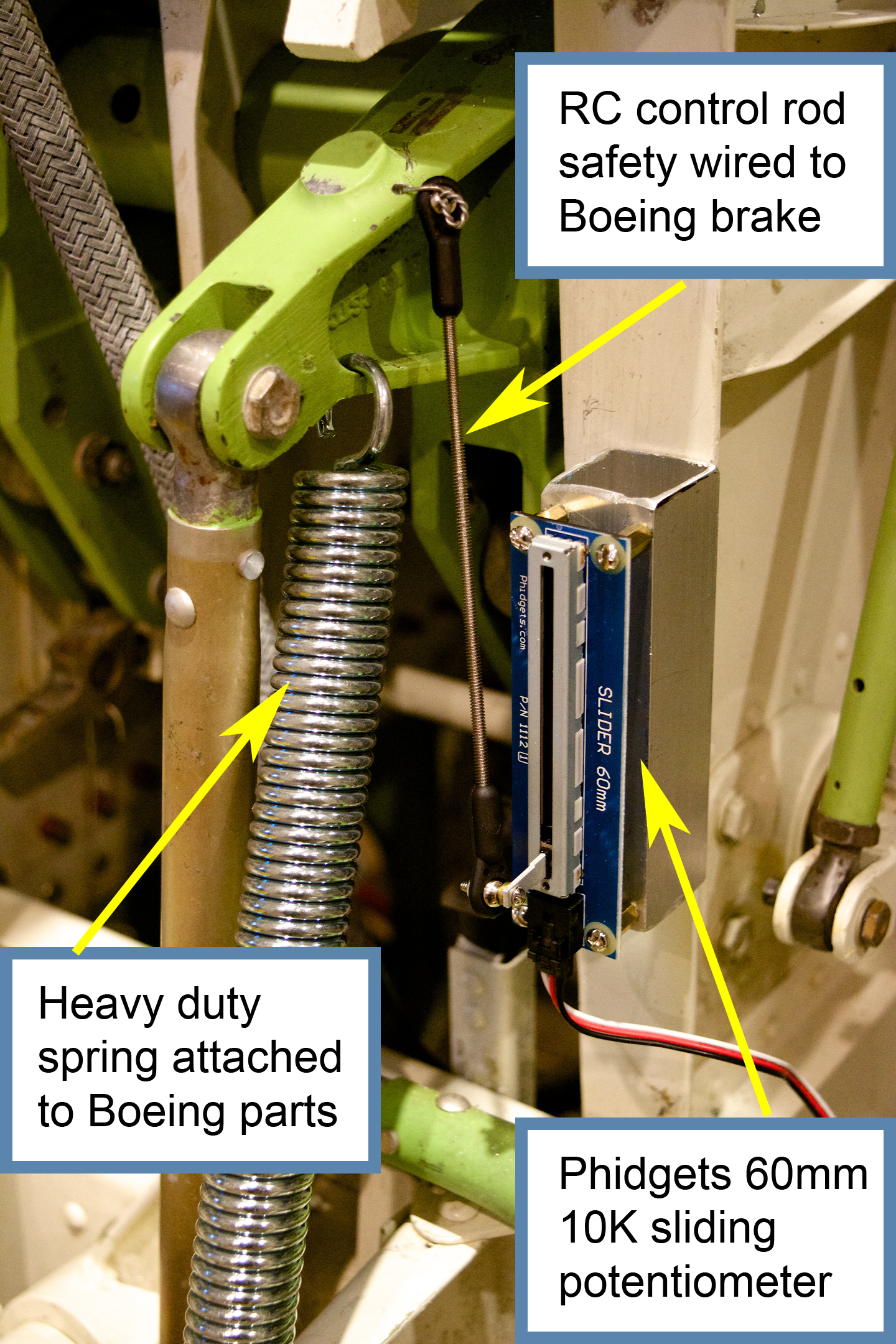
Existing Boeing brake mechanism fitted with slide potentiometer to measure brake excursion.
Having overcome the major hurdle of implementing dynamic force feedback, I have been busy performing other tasks that will be most easily accomplished while the floor remains in vertical position. These include wiring the brakes and stick shakers, as well as rewiring the throttle quadrant with salvaged AMP cannon plugs that allows the interface cards to easily detach from the mechanical parts of the unit. I used a 55 pin plug for the switches and pots, and a separate plug with larger 16 gauge pins for the power connections.
The floor section just prior to flipping back to horizontal. Various cable bundles are visible for connection to components above the floor. Kill switches for dynamic control loading motors are seen just inboard and forward of the FO control column.
I spent at least a week going over the underside, testing all the functions and tidying up cable runs. Once this section is put down into its final horizontal position, there will be only 20 inches between the flight deck and the floor of the basement, so I will still be able to get in and work on things, but it will be a lot less convenient and probably a lot more likely to induce neck and shoulder pain. Twenty inches seems like a lot, but that’s the distance from the flight deck to the floor, and there are a lot of mechanical parts in between, such that there won’t even be room for a creeper.
The floor, finally back in normal horizontal position after years of configuration. Various cable bundles come up from below the floor, to be used as components are added above. All cables below the floor run forward, where computers and power will eventually be located.
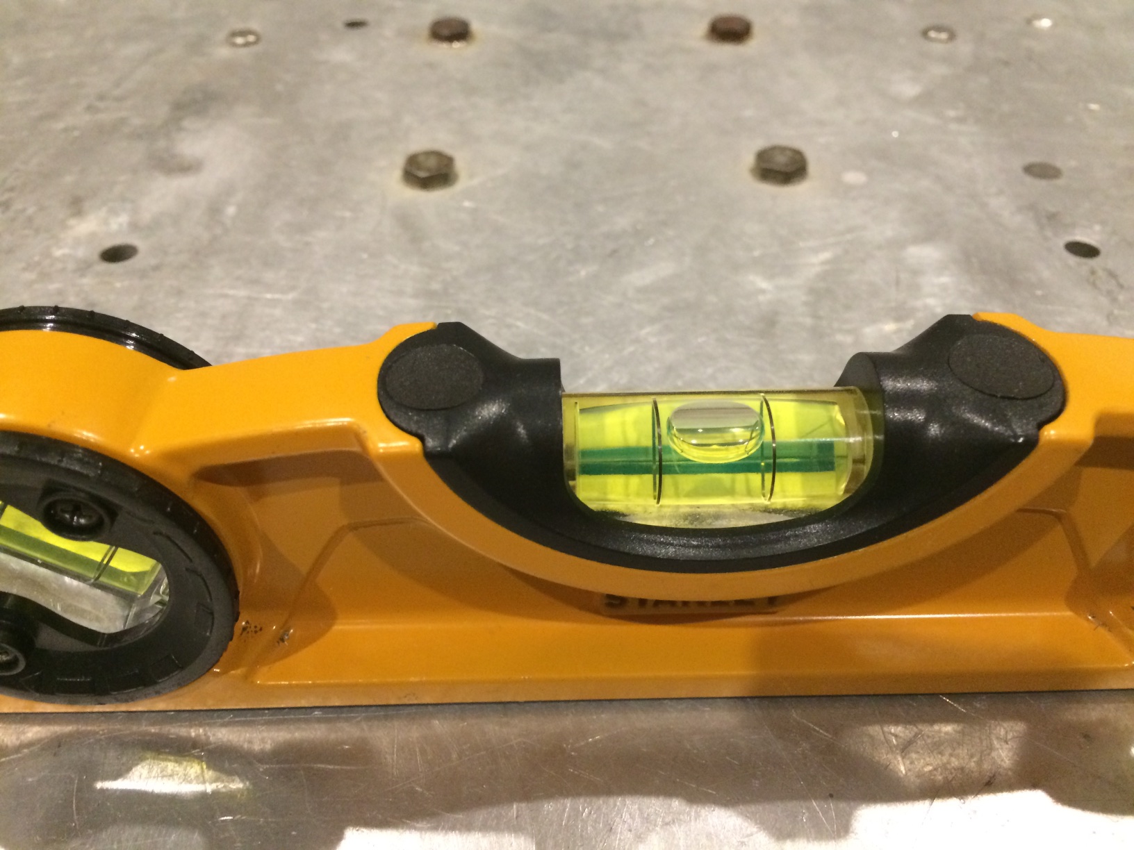
The day finally came, and after one final cleaning, I cut the heavy cable ties holding the floor section to the ceiling joists above, and started sliding the section as far forward as it would go in the room. I called my buddy Adrian, a senior F/O at jetBlue, to come over and help me lower it. I figured it would be pretty easy for two of us to lower it down, as it seemed to me that most of the weight was concentrated in the yoke and rudder mechanisms located fairly far forward. It wasn’t that hard, but the aft end was quite a bit heavier than I thought. Luckily Adrian’s fiancee Kelly, herself a Captain and check airman at Frontier, was there to help place the aft floor supports, which I had made from short sections of 6×6 and 2×6. Once we got it down, a quick check revealed that the flight deck was perfectly level in all directions. Looks like my cuts and indexing were precise enough!
The cuts must have been precise enough: a perfectly level floor with no shimming required.
Welcome to my website. About 4 years ago I became obsessed with building a full size, fixed based Boeing 737NG simulator. I started by buying parts, both used pieces from actual aircraft as well as new pieces from vendors that manufacture parts for the simulator market. I am proud to be a crazy simulator builder and I started this site to share my madness with the world.
I plan to update frequently with pictures and blogs about my progress on the sim. My progress so far has been hampered by my inability to sell a troubled asset: a luxury 2 bedroom condo in Arlington, Virginia. I bought the apartment in the Fall of 2007, just as the real estate bubble was starting to burst. I had my sim set up in the second bedroom of my condo, but then had to remove the fledging project after my girlfriend (later my fiancee and now my wife!) moved in during the summer of 2008 and we decided to put the condo on the market.
My sim, circa 2008, back when we were living together. Real Weber seats, MIP and pedestal by CockpitSonic, overhead mounted on the wall (for lack of a better place), and Optoma short throw projector mounted on the ceiling.
My real estate agent took one look at the sim and said, “you’re going to have to remove this if I’m going to have any chance of selling this place.” I knew he was underestimating the mass appeal of a full size transport category aircraft cockpit, but I decided to trust the professional and moved everything into storage, where it remained until February of 2010. My other hobby is flying real airplanes, and it was during that month that I lucked into a hangar at Manassas Regional Airport. This particular hangar is an end unit that has about 300 extra square feet of space off the right wing, so the sim came out of storage and work started up again.
Starting to set up the sim in my new hangar. Shell framework, dual linked flight controls and floor by Northern FlightSim. Fiberglass shell is visible up against the wall in the background.